Good catch - I accidentally had a permanently fixed stand on the lower-left corner that was causing these errors in the free version. Oops! It didn't affect anything in SSSS or CCCC, obviously, but did shift the low-frequency modes around for FFFF. I must've been experimenting with that at some point and forgot to set it back.From the EPS impedance plot with PETTaLS, the lowest frequency peaks are not aligned with the measurement.
I'll upload a new version soon that gets rid of the stand and also includes the coupling resonance.
In the meantime, here are some updated results:
Happy those test cases helped in debugging. The fix should solve the frequency shift, the asymmetry in the velocity map and the unexpected peak in the FR.Good catch - I accidentally had a permanently fixed stand on the lower-left corner that was causing these errors in the free version. Oops!
We have now 3 test cases: PS CCCC, EPS FFFF, PMMA FFFF. I have prepared 2 others but I have to learn more from Eric's tap test method to get the materials parameters.
I don't know what is the features road map for PETTaLS but I have 2 have in mind :
- better plots : my preferred option would be a text export compatible with REW (csv format). In a previous version the plots were opened and enlarged in a floating window which I prefer to the current small plots.
- All the test cases confirm the LF roll of due to the open back and its effect in the 200...400Hz range. Not an easy topic but needed in my opinion for such application.
Christian
Eucy,Christian... I'm interested in which models you've tried and why you consider them to be no good...
Here is a first version of a paper about damping.
Don't be afraid by the mathematical aspect of the document. It is a way for me to keep notes of what is in the python code. It is also an opportunity to think differently trying to explain what is implemented.
Thanks to that, I found a bug which i think fixed now in some sign mismatch. The damping parameters are now positive as expected!
In the second part of the document are plots that show the effect of each type of damping.
The parameters are not well adjusted. It is the result of few tests.
The main point is probably how the model acts in the frequency range.
The SPL level of the frequency simulation is not aligned on the SPL level of the modal decomposition; A fix to come.
Christian
Attachments
@homeswinghomeWe have now 3 test cases: PS CCCC, EPS FFFF, PMMA FFFF. I have prepared 2 others but I have to learn more from Eric's tap test method to get the materials parameters.
@EarthTonesElectronics
In trying to provide Christian with the best possible characterization of the elastic constants for various panels, I did a series of FEA trials to show how each of the six elastic constants for orthotropic plates influences the natural frequencies. The main purpose for me was to help make my crude trial and error method for evaluation of the elastic constants just a little more rigorous/reliable. Take a look here (or at least pretend to!).
Effect of Elastic Constants on Natural Frequencies
Christian,
I realize this isn't the answer you are looking for regarding the real meaning of the additional shear moduli, but at least it gives you an idea of their impact.
Eric

@EarthTonesElectronics
Dave,
Christian's posts reminded me of something I've been meaning to ask for some time but keep forgetting. I'd be very interested to know a bit more about how you estimate (a) the elastic properties of plates and (b) their Q value. Not necessarily every detail, but at least the basic gist.
Thanks,
Eric
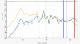
Here are some updated results matching Christian's tests from PETTaLS now that I've removed that pesky stand and added in a simple unbaffled correction. (Black is the new set of results)


I haven't been very good about answering questions lately - let me try to get to some of that...
I'm hoping to have the new PETTaLS versions uploaded today, for everyone who's paying attention to that. I'm tracking a lot of downloads, so it seems like a decent number of people are paying attention!
I haven't been very good about answering questions lately - let me try to get to some of that...
Surface velocity measurements. The Q of all modes seems to be pretty constant when measuring average velocity. I don't know why the values are so different in the impedance measurements - probably something to do with the added stiffness of each mode at the exciter location. The surface velocity right at the exciter point isn't predicted as well by my models as the average surface velocity, so I would assume that the corresponding impedance would also not be predicted as well.Could you explain the reasons that lead you to adopt the PETTaLLS Q values?
It's all velocity measurements. For elastic properties (which is my case is just Young's modulus), I just measure the density of the material with a scale and then play around with numbers in simulations until the mode frequencies match up. I think I've really only ever done this with poster board materials, though, so for everything else I look up publications and use numbers that more qualified people have figured out!I'd be very interested to know a bit more about how you estimate (a) the elastic properties of plates and (b) their Q value
I'm hoping to have the new PETTaLS versions uploaded today, for everyone who's paying attention to that. I'm tracking a lot of downloads, so it seems like a decent number of people are paying attention!
Hello Dave,Here are some updated results matching Christian's tests from PETTaLS now that I've removed that pesky stand and added in a simple unbaffled correction. (Black is the new set of results)
Very good!
Would you mind to explain me your model of unbaffled correction that I implement it in the python script? I have at least 2 other test cases which are going to be documented enough (I mean impedance + FR + material characteristics), Eric made the proposal of 2 others.
In parallel I found papers about edge diffraction and open baffle model. I just started to implement it. The advantage of the model of diffraction of those papers is they are valid on wider angle than the previous one.
What is puzzling me is the slope of the diffraction based model compare to the measurement.
Christian
Just a simple high-pass filter, as I mentioned in an earlier post, where the dimensions of the panel determine the cutoff.Would you mind to explain me your model of unbaffled correction that I implement it in the python script?
Here are updated simulation results (blue) matching one of your tests from a while ago. Not the right exciter model, but it seems to work pretty well anyway!
Attachments
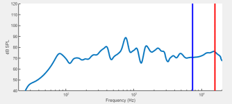
Whaou! It becomes very impressive!Just a simple high-pass filter, as I mentioned in an earlier post, where the dimensions of the panel determine the cutoff.
May I know how you mixed the dimensions to get the frequency cut off?
Christian
- Home
- Loudspeakers
- Full Range
- PETTaLS Flat Panel Speaker Simulation Software