Thanks PRR;
BTW; I have powered up the amp again with a 125 Ohm load connected, and drove it to about 5 Volts (RMS) output. It seems to run perfectly, and I limited this test to 15 minutes.
Further question; Why did a device fail in the B- rail, and then in the B+ rail?
A: Did the short in Q117 (B- side) stress the devices on the B+ side? I always thought that the speaker load took the brunt of the 'short-circuit' current, with the opposite rail being in 'cut-off' mode.
or B: Could it just be that the initial abuse that caused damage to the B- rail, also stressed the B+ side?
Yet another question; am I at the point where ordering two sets of outputs (NPN and PNP) is a good gamble-----or are the further tests that could be performed, to verify that this amp is a good candidate for a transplant!
Thanks again, Peter
A shorted output on one rail will always stress the ones on the other. That's why you replace them all when one fails. So you don't keep replacing them one at a time until eventually you get them all anyway.
When running with some outputs removed, you want equal numbers so the quiescent bias is the same per output device in both rails. If you get a poor match between the individual ICQ"s you need to stop and address it.
You need to test into that 125 ohm load all the way to full output swing. You may have hidden problems in the high rail transistor banks that you won't see until you test them. Get it working with one known good output per rail per bank. That's what you use outlier units for (when buying a rail of them to match for paralleling). When it runs at full signal, with the rail switching looking clean, stable bias current, and no oscillation - then you're ready to fire it up with brand new full (matched, for vbe) output banks.
And check all your commutation diodes while you're at it.
Hi wg_ski and all;
I checked diodes again, all good, and powered up the amp. I drove the amp to 'full swing' into a 125 Ohm power resistor. The amp clipped evenly at 81 Volts RMS. Minor panic as I smelled smoke! Fortunately, it was my 10 Watt power resistor, objecting to the 81 Volts (52 Watts)-----Another rookie mistake!
Apart from smoking my load resistor, the amp seemed to perform perfectly. I could see no glitches on the scope, I was particularly focused on the sine wave, half way up from the traditional (zero or crossover) region). It seems to transition smoothly from the Low to Hi rails.
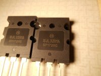
Its seems I may soon be in the Output Transistor Matching game. I am open for suggestions but my 'googling' so far has determined that the best substitute for the obsolete 2SA1302 / 2SC3281 is: ON Semiconductor MJL1302A / MJL3281A. I have used ON Semiconductor replacements in one of my PHASE LINEAR 700B's. At the time , I simply replaced all 10 outputs in one channel, without 'matching' the new devices. I have 'beaten the daylights' out of this PHASE on some subsequent occasions and nothing has blown up (yet). Could I have just been lucky with that batch?
I don't want to re-hash information that has been well covered in this, and other forums, but....having read every relevant thread on diyaudio and a few other forums, I'm still confused.
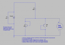
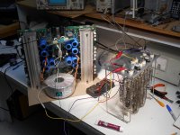
Attached is a rig that appeals to my limited skills and lack of budget. I am sorry for not recalling the author and attributing due credit;
I checked diodes again, all good, and powered up the amp. I drove the amp to 'full swing' into a 125 Ohm power resistor. The amp clipped evenly at 81 Volts RMS. Minor panic as I smelled smoke! Fortunately, it was my 10 Watt power resistor, objecting to the 81 Volts (52 Watts)-----Another rookie mistake!
Apart from smoking my load resistor, the amp seemed to perform perfectly. I could see no glitches on the scope, I was particularly focused on the sine wave, half way up from the traditional (zero or crossover) region). It seems to transition smoothly from the Low to Hi rails.
Its seems I may soon be in the Output Transistor Matching game. I am open for suggestions but my 'googling' so far has determined that the best substitute for the obsolete 2SA1302 / 2SC3281 is: ON Semiconductor MJL1302A / MJL3281A. I have used ON Semiconductor replacements in one of my PHASE LINEAR 700B's. At the time , I simply replaced all 10 outputs in one channel, without 'matching' the new devices. I have 'beaten the daylights' out of this PHASE on some subsequent occasions and nothing has blown up (yet). Could I have just been lucky with that batch?
I don't want to re-hash information that has been well covered in this, and other forums, but....having read every relevant thread on diyaudio and a few other forums, I'm still confused.
Attached is a rig that appeals to my limited skills and lack of budget. I am sorry for not recalling the author and attributing due credit;
Attachments


Just thinking out-loud;
I received an email response from Peavey, advising me that Bias is adjusted for 7 millivolts across the .33 Ohm emitter resistors. This indicates an idle current of .148 mA. (seems very low, but I will power up the good side of the amp to verify this)
If V be is compared at idle current and at 1 amp, would this require a value for R 1, in the "Simple test circuit" above, of 160 k Ohms, and 24 Ohms, respectively, using a 24 V regulated Supply. (R= V/I , V=24 volts)
Am I on the right track? Thanks again for all the guidance, Peter
....Peavey, advising me that Bias is adjusted for 7 millivolts across the .33 Ohm emitter resistors. This indicates an idle current of .148 mA. (seems very low....
On my abacus, 0.007V on 0.33 Ohms is 23mA. (115mA for five pair.)
On an over-simplified analysis, this does seem to be marginal for crossover. However I'm not going to re-look the whole plan. This is not a "soft" hi-fi amp, it is a LOUD stage amp. Crossover is not the sin it would be for background levels in a living room.
Thanks PRR;
OOPs, yes, my error. Thanks for the correction. For 23 mA, R1 in the test rig in entry #64 above, would be about 1 k Ohm, with a 24 Volt supply.
I realize this is not an amp for a purist, but, at the risk making the my fellow Audio enthusiasts cringe, it might be quiet enough for sub-woofers in a large home theatre system (and have a helluva punch!?).
BTW, What is your opinion regarding the validity of the test jig in entry 64?
R1 in post 64 is 100k, not 1k. Looks like an easier way to match transistors than the way I have been doing it which is like post 63 but using a 100 ohm base resistor, not a 10k pot.
I think post 64 measure Vbe which should tell you somthing about process matching, if not the actual gain.
Glad you're making progress. Yeah, I wouldn't use one of these in my living room; one burp on switching the RCA plugs would blow my ears out. But I have 101 db @ 1w1m speakers. Most speakers are less efficient. But an amp like this should never run at 1 W, so 23 ma on bias should be fine. Heck, my dynaco ST120 runs at 20 ma bias current and I don't hear annoying crossover. (but it has one output transistor pair). Without the djoffe bias control circuit, ST120 zero volume bias was zero and yes, that was annoying.
You want to match at or near 23mA. Matching for hFE isn't necessary, so setup in #24 is all you need. The higher value resistor is fine for matching diff pairs, but you want a higher current for outputs.
Most of the time just getting a batch from the same lot is a good enough match. They would be within a few millivolts. You can do better, and with this kind of energy storage on tap it's a good idea. The old Phase is nothing special in the output stage, and runs pure class B. I've built plenty of amps with similar output stages, and even run them into AB. And not bothered to match devices except just using ones from the same tube with the same date code. I'll still get near equal quiescent currents in all the devices. The two times I didn't he outputs ended up being fakes. The unequal current was what clued me in there was a problem. When I started messing with really high voltages and higher classes of operation I paid more attention to the matching. It really isn't a hardship if you buy your devices 25, 50, or 100 at a time. The unmatched outliers make good drivers. I've always paid close attention to matching diff pairs, because the difference in distortion is nothing short of shocking.
Most of the time just getting a batch from the same lot is a good enough match. They would be within a few millivolts. You can do better, and with this kind of energy storage on tap it's a good idea. The old Phase is nothing special in the output stage, and runs pure class B. I've built plenty of amps with similar output stages, and even run them into AB. And not bothered to match devices except just using ones from the same tube with the same date code. I'll still get near equal quiescent currents in all the devices. The two times I didn't he outputs ended up being fakes. The unequal current was what clued me in there was a problem. When I started messing with really high voltages and higher classes of operation I paid more attention to the matching. It really isn't a hardship if you buy your devices 25, 50, or 100 at a time. The unmatched outliers make good drivers. I've always paid close attention to matching diff pairs, because the difference in distortion is nothing short of shocking.
...opinion regarding the validity of the test jig in entry 64?
As has been noted: that's scaled for 0.1mA, which is AWFUL low for Power transistors. May make sense for input devices. As said, 1K or 390r may be more your size.
Otherwise-- what more could you want? Oh, there's many-many "improvements" possible. Some measure of hFE may be relevant. Measuring with Vce>10V may be more appropriate than at 0.6V. All of these add complexity, and more opportunity for arithmetic mistakes.
Hi Folks, just an update:
The transistors are ordered---feels like Christmas! I order 10 each MJL1302AG and MJL3281AG. I went against the advice of wg_ski because the girl at Newark could not assure me 25 devices would be from the same batch, (and secondly; I'm cheap!).
Here is my "Absolutely Simplest Transistor Tester Ever"; I have been trying it on the remaining low rail PNP and NPN devices, which have now been removed.
Attachments
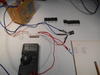
This is the most straight forward arrangement I could find. I am re-posting the schematic below. As advised; R 1 is 1 k Ohm, this allowed a test current of 23 mA with a 24 V supply. My power supply is well regulated, so R 2 was not necessary ( I believe).
I connect 2 blue clips (on Base and Collector) for PNP, and 2 red clips on B and C, for NPN. I found that readings dropped about 1 mV, at the 10 second point, without much more change, even at 1 minute.
I felt no temperature increase in the transistors (tested here without heat sink), and only just perceptible temp increase in R 1. Obviously, my readings should be talking at the same point in time, but am I correct in assuming that at 23 mA, timing is not critical?
Thanks again, all, Peter
Attachments
As far as used transistors from a blown up amp, I find the ones that will explode in future have a little lower Vcb than the others. Meter diode test. Confirms by measuring current Vceo with a 12 v supply. That is with base open, will the collector hold off 12 vdc? How many ma or microa? Stressed ones leaked.
Newark won't guarantee anything, but if you count on human laziness, if you order a rail of 25 they are not likely to cut two different rails and tape the end of both if they can get away with it. I ordered +2 spares and found exactly two with better gain than the other 10. Three extras would have been more secure.
Newark won't guarantee anything, but if you count on human laziness, if you order a rail of 25 they are not likely to cut two different rails and tape the end of both if they can get away with it. I ordered +2 spares and found exactly two with better gain than the other 10. Three extras would have been more secure.
The Tranny's are here!---(I never felt right about that abbreviation).
All the NPN's have the same date code. The lower number is referred to as 'date code' on the pack slip.
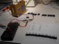
Initial Vbe test were disappointing, but after allowing my test apparatus to warm up (connecting the 1 k Ohm resistor directly to the 24 V supply for 1 hour), results were more consistent.
All the NPN's have the same date code. The lower number is referred to as 'date code' on the pack slip.
Initial Vbe test were disappointing, but after allowing my test apparatus to warm up (connecting the 1 k Ohm resistor directly to the 24 V supply for 1 hour), results were more consistent.
Attachments
Here are my results; column 1 was from a cold start (all readings were taking after a 10 second count, the 10 second wait typically resulted in a 1 mV drop)
The 3rd and 4th column were taken after the 1 hour warm-up of the test jig.
I feel I may be 'out in left field' here, but my plan was to repeat this measurements a number of times, until I see a definite trend that is specific to each transistor.
I am open for suggestions regarding changes to my test method, but on the forth time around, the readings only varied from .585 mV to .588. The increase seemed to follow the order of my testing sequence, so the most obvious procedure change would be to reverse my testing order. ( I'll get back with those results asap).
My thinking was to select the 5 highest (or 5 lowest?) devices, rather than taking 5 out of the middle. This would leave me with a more closely matched set of spares. Is this foolish?
I really appreciate any guidance, thanks again, Peter
Attachments

Hi Folks; I think I'm winning!
The new outputs are installed and the amp has been powered up by variac. Nothing blew up! And now the bias situation. Some time ago, I pestered the Peavey Service department for info regarding this amp, and they were kind enough to send a pdf about the operation of the protection circuitry and this email. re; bias:
Peter,
Not sure if you received a copy of this document but it explains the ramp up circuitry in the amp.
Bias is set by selecting an emitter resistor on one of the channels and measuring it (usually the good channel), then measuring the same resistor on the other channel to see how
close they are (adjust to match the good channel). You should be seeing around 7 millivolts drop across the resistor. This is done with no load connected to the amp nor with an input signal.
I hope this helps,
Grant.
With no load and no input connected, I found Emitter resistors on both channels to have 1.5 to 1.6 mV drop. ( One resistor on the 'good' side was 1.3 mV, but I hate to think about that too much---should I worry?)
It does seem extreme to adjust the bias to 7 mV, when at the moment, the bias seems t match the functioning side exactly. Expert opinions would really be appreciated at this point. I then connected signal and dummy load to the amp. I was able to develop about 29 Volts ( 105 Watts )across the load, electric furnace elements reconfigured to 8 Ohms, but had to stop there to avoid overloading my variac/AC amp-meter setup.
I think I am ready to power up the amp directly, without variac and check for max power, balanced clipping etc, but I would like to wait for 'any last words' from the helpful people who have been following this thread!
PS: I did not see any crossover distortion on the scope, but am I correct in assuming that things would have to be pretty bad before they can seen on a scope trace?
Thanks again, everyone for your help, Peter
Attachments
I can hear crossover distortion, sort of. Most audible at very low volume, which is about .5 W/ch on my super efficient speakers. If your like house music, electro dance, compressed TV commercials, etc, I wouldn't worry about it. If you like classical music with a high crest factor, I follow the Peavey spec. 7 mv across 0.33 ohms is 2.3 ma, certainly not likely to overheat any TO220 or TO247 transistor. At 29 v you're not going to see crossover distortion. 0.5 v out, yeah, you probably can. I don't have a working scope.
BTW turn it all the way and see how high can go if the wiper oxidizes and loses contact. 20 ma is pretty safe in TO3, 100 is not unheard of. This unit does have a fan, so there is some backup. Of course cold idle current is much much less than hot bias current.
Paranoid people replace a bias pot with a fixed resistor after figuring out what setting they need for the transistors made that day. My "closed loop" bias control circuit supposedly set to 20 ma had a b-e junction let go and it ran at 200 ma for some months. I had fans on the improved heat sinks so the output transistors weren't damaged.
Last edited:
Thanks indianajo:
I forgot that the cross-over distortion is 'hiccup' of fixed amplitude (if I understand correctly) so of course, the larger the signal, the smaller it will appear.
I will run the amp to clipping, to see if it holds together and also observe both channels with the tiniest possible signal.
I will report back asap---unless it blows---in which case my response will be delayed by a mood altering beverage break!
- Status
- Not open for further replies.
- Home
- Live Sound
- Instruments and Amps
- Pet Peeve Peavey (GPS 3500)