if you don't mind waiting a few days i'll see if i can scan the hardcopies i've got (if that doesn't work i could snail mail you a photocopy)
Wow! thanks turk. I can wait for the scan! I used to feel better with a paper copy, but I now have a big monitor by my bench.
You will find the schematic very similar to the PL700 series 2. With only +/- 80 volt supply, where it is extremely reliable In comparison. But the build concept is very much a BGW.
SJ6343 is the same as 83180. 704 means NPN To-3. PV's replacement manual states that it is a 180V device - likely a selected 2N3773 because the old aluminum TO3 pre-dates the 15024. But it does call for the 15024 as the modern replacement. I put D424's in them before the 15024 was widely available (and Original D424's were four bucks a pop from MCM).
I would ditch all the old aluminum To3's. They have a limited service life, as the die attach fails after about 5000 thermal cycles. Very much like the modern surface mount HExfets they put in the Behringer iNukes - which don't even last 1000. The steel To3's with the copper heat spreader are good pretty much indefinitely if you don't just blow them due to overheating or massively violating SOA. I would also test those no-name 15024s that someone put in the driver positions. Just to make sure they aren't fake.
Thanks, wg_ski;
Looks like I'll be ordering a "tube" of ON semi MJ15024's I will steal some time today to fire this amp up by variac, it has a note indicating one channel not working. I believe the 15024 was a possible substitute for the PL700B, but I went with MJ21195's--too bad. Should I order a ship-load, in case my Phase's go 'fins up' (again)?
Also, regarding the aluminum TO3's, the change to steel packages looked 'cheap' to me but it never occurred to me that the higher expansion rate of aluminum could lead to problems--thanks, learning already!
BTW; I know my PL700B's are quasi-complimentary, but aren't the Series II's full complimentary?
Momentarily, I will fire up the CS 800, but I will have to really fall in love with this amp before I sink almost $200 (Canadian) for a complete set of outputs.
Merry Christmas All!
Depending on the phase of the moon, 21194's are often cheaper. But not always. They are better, and can be used anywhere the 15024 can. I'd buy whichever is less for the PV or a PL400. For the 700 I would have gone with the 21194 because of the extra SOA. The bigger PL needs it.
The series 2 was made both quasi and full comp. The ones I had were quasi. When I built my CS800/BGW "clone" I went full comp.
The series 2 was made both quasi and full comp. The ones I had were quasi. When I built my CS800/BGW "clone" I went full comp.
I thought you were mistaken re 21194's, but my error. I actually used 21196's. I cannot see any difference's in the info pdf's , between 21194's, 21196, or 15024's. I have the CS400 projects ahead of me, so I am hopeful that they also use the same device.
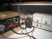
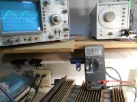
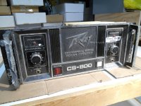
So the CS800 has been powered up; 84 Volts DC on chan A, chan B working; 51.5 Volts across the 8 Ohm dummy load. Not bad! 331 Watts. This thing is as old as the hills, and still exceeding specs by a healthy margin.
My intention is to try to get chan A functioning. From what I have learned, I can remove the shorted devices and (fire) it up with an equal number of good devices on the B+ and B- rails.
I will have check the amp pcb, I have heard some scary stories of smoked pcb circuit paths and Triac protection circuit, which at this point is still a mystery. Hope to report back asap, have to go shovel the drive way, and want to do it while things still look optimistic!
Attachments
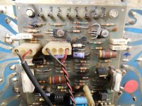
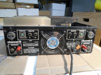
This CS 800 has had a tough life! (probably like most of them) Multiple repairs, some bulging electrolytics, toasted transistor (are they pre-drivers?), and it looks to me like bad connections at the feed-through prongs. And that is just the visible trouble.
There is an eight of an inch of nicotine flavoured fur in the bottom of the amp but I don't want to blow it out until I can remove the volume pots. I think the compressed air might blow dirt INTO the pots.
There is an eight of an inch of nicotine flavoured fur in the bottom of the amp but I don't want to blow it out until I can remove the volume pots. I think the compressed air might blow dirt INTO the pots.
Attachments
Thanks Michael;
This is the clearest version of the schematic for what seems to be my amp. The components are not labeled R1, C2, etc on the (series A) schematics that I have seen so far. It looks like most of the trouble is on the driver board, I am using a component layout (image) from a series "C", at this point, hoping that they are similar.
This is the clearest version of the schematic for what seems to be my amp. The components are not labeled R1, C2, etc on the (series A) schematics that I have seen so far. It looks like most of the trouble is on the driver board, I am using a component layout (image) from a series "C", at this point, hoping that they are similar.
Attachments
Hi turk;
Thank you so much for your offer to scan your original. If I haven't extinguished your enthusiasm, would you have a clearer image of component layout, as on page 3 of this pdf?
Thanks, Peter
Thank you so much for your offer to scan your original. If I haven't extinguished your enthusiasm, would you have a clearer image of component layout, as on page 3 of this pdf?
Thanks, Peter
Attachments
Last edited:
This is better than Chess!
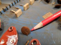
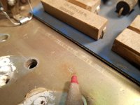
So far, there has to be at least five reasons why this channel won't work. In removing the TO3's from the heat sink, I found the emitter pin socket to be opened or bent, to almost twice the pin diameter.
A ceramic disc capacitor on the (power) pcb appears to have made electrical contact with the heat sink;
Attachments
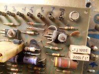
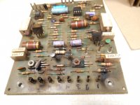
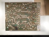
There is some 'sustantial' damage to the driver board. There was 80 something volts on the output terminal, but the TO3 drivers and all outputs checked OK by Fluke meter diode test.
I am determined to make this amp look and sound like Michael F's at;
Peavey CS 800 heating
Very Clean!---In the mean time, here's the under side of the driver pcb;
PS: this driver board looks identical to the CS 400 driver pcb (except that B+ and B- are 59 Volts, rather than 81. Are they interchange-able? I have also inherited two dead CS 400's.
Attachments
Uh, 2v test doesn't screen out over stressed transistors. Use a 12 v power supply or something similar, put in series with a 10k or 47k resistor. Try Vceo ie base disconnected. Current should be low one or 2 digit microamps; if you have nearly 250 microa with the 47k resistor your transistor leaks. I use a car battery charger followed by a filter cap. Plus to collector on npn, to emitter on pnp. I use alligator clip leads, which were cheap at radio shack but newark is now getting $7 for each one. I think Oreilly's auto supply is getting about $4 for two alligator clip leads from Dorman. Dorman ones not rated for 600 v of course.
Last edited:
- Status
- Not open for further replies.
- Home
- Live Sound
- Instruments and Amps
- Pet Peeve Peavey (GPS 3500)