no speaker protect installed or any zobel in my amps sir... I just directly connect the out-put to the speaker terminal...


Hi Shaan and others,
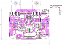
Here is yet another version of PeeCeeBee (Not tested). I basically followed Jason's Schematic and layout but for 2SJ1058/2SK162 pair. Only additional change is the provision for MT trimmer resistor(3296W) in place of off1-off2 , as most people in their build in this thread mentioned that they used trimmer to get the final values of off1-off2, which then were replaced with closest resistors. Note that the 2SJ/2Sk pair are intended to be mounted from the bottom of the board.
Any comments from any members are welcome. I has been a good and learning layout exercise for me.
reg
prasi
Attachments
Dear prasi,
What is the heat sink size and how are you going to mount the PCB wrt the heat sink?
gannaji
What is the heat sink size and how are you going to mount the PCB wrt the heat sink?
gannaji
Hi gannaji,
Pl have a look at PMI version of vssa , and also borys hexfet amps to get an idea. The sj/SK 's mount from the bottom side. For VAs trannies, see Jason's to-3 version of peeceebee.
Reg
Prasi
Pl have a look at PMI version of vssa , and also borys hexfet amps to get an idea. The sj/SK 's mount from the bottom side. For VAs trannies, see Jason's to-3 version of peeceebee.
Reg
Prasi
Dear Prasi,
Probably, my question is not phrased clearly.
Considering the range of heat sinks available in Indian market, did you have a particular size of heat sink in mind with a specific location for the SJ/SK to be mounted?
G Annaji Sarma.
Probably, my question is not phrased clearly.
Considering the range of heat sinks available in Indian market, did you have a particular size of heat sink in mind with a specific location for the SJ/SK to be mounted?
G Annaji Sarma.
Hi Annaji,
If I understand correctly, the peeceebee /vssa dissipate quite a bit of heat even during idling. I feel something like 100mm wide x 250mm length x 75mm height heat sink may be sufficient, may be shaan/Jason can give more insight. Pl check gaj supply website, they have variety of heat sinks.
reg
prasi
Hi Prasi,
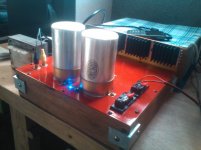
Apply some creativity, here's how I did it. A not so thick heatsink but I added
multiple fins as heat dissipator, works very good as well 😀
Hey thats really good. Can post a shot of whats the inside arrangement? Unfortunately I am not so skilled as it comes to physically building something.
reg
prasi
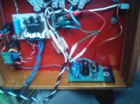
DIY At its best! congrats😀😀...not so clear image...work in progress (mono) but the board was so tiny, It fits exactly on the heatsink (vertical mount) 😀 The transformer will sit on top next to the vintage caps "ala" tube style. 😀

Hi prasi. 
The layout looks good.
Only those thin traces near C5 and C6 troubles me a little. As these carry the ground potential I think replacing the traces with pads for double jumpers will be a lot better electrically.
Thanks for sharing ^^
shaan
The layout looks good.
Only those thin traces near C5 and C6 troubles me a little. As these carry the ground potential I think replacing the traces with pads for double jumpers will be a lot better electrically.
Thanks for sharing ^^
shaan
Last edited:
Hi prasi.
The layout looks good.
Only those thin traces near C5 and C6 troubles me a little. As these carry the ground potential I think replacing the traces with pads for double jumpers will be a lot better electrically.
Thanks for sharing ^^
shaan
Hi Shaan,
Are you talking about the faint blue lines/traces? those are jumpers and I will make two of them jumpers as you suggested.
reg
Prasi
Hi prasi.
The layout looks good.
Only those thin traces near C5 and C6 troubles me a little. As these carry the ground potential I think replacing the traces with pads for double jumpers will be a lot better electrically.
Thanks for sharing ^^
shaan
Hi Shaan,
here is the modified layout as per your suggestion. I have also tried to connect zobel under the board as shown. Is it advisable?, because the trace connecting with zobel passes very close to the "S" of 2SJ162.
reg
prasi
Attachments
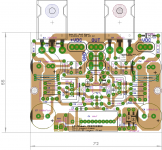
I think increasing the board size a bit will solve the accommodation problem for all the parts near the power section. Try not to overlap a component's marker by another and I think this will leave ample space for adequate placement of the zobel and the triple jumpers. And also, the zobel should be terminated at the center ground point, not on either side. 
I think increasing the board size a bit will solve the accommodation problem for all the parts near the power section. Try not to overlap a component's marker by another and I think this will leave ample space for adequate placement of the zobel and the triple jumpers. And also, the zobel should be terminated at the center ground point, not on either side.
thanks for your reply, I will leave out the zobel and connect it at spk terminals. I wanted this to be the smallest PEECEEBEE with film i/p cap and with trimmers and all TH parts😉. OK I will re-work the layout a bit.
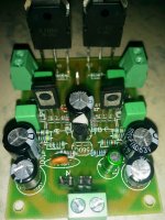
my first attempt, hope many more will come, just finished , not connected yet
thanks to shaan who helped a lot , whos pcb i am using , and thanks to LC and all fellow diyers here with out them this would not be possible
thanks to shaan who helped a lot , whos pcb i am using , and thanks to LC and all fellow diyers here with out them this would not be possible
Attachments
- Home
- Amplifiers
- Solid State
- PeeCeeBee