I attached the sim files. The models I use are the Cordell models.P.S.: if you can, please post the simulation, I know I would like to see it, and other people might want to see it too.
Attachments
Last edited:
...One thing I found today is that if you test with an unconnected/ungrounded signal cable which is long enough, the circuit can be made to oscillate very easily within the bandwidth of the input filter...
I made an MW receiver from my DOZ. Touched the open input header and it was 'on air' through the speaker. 😀
niko, what you going through is same as me.
with bd139/140 .. no cap. compensation only zobel it stable
with sa/sc 1381E/3505D , sa1380/3502 no cap, only zobel it oscilate
with sa/sc 1381E/3505D , sa1380/3502 47pf. cap with zobel it stable
need to try sa1360/sc3423
with bd139/140 .. no cap. compensation only zobel it stable
with sa/sc 1381E/3505D , sa1380/3502 no cap, only zobel it oscilate
with sa/sc 1381E/3505D , sa1380/3502 47pf. cap with zobel it stable
need to try sa1360/sc3423
Nafniko, what you going through is same as me.
with bd139/140 .. no cap. compensation only zobel it stable
with sa/sc 1381E/3505D , sa1380/3502 no cap, only zobel it oscilate
with sa/sc 1381E/3505D , sa1380/3502 47pf. cap with zobel it stable
need to try sa1360/sc3423
I feel that you showed some post a waveform as result to 500 KHz,can you give me the post ?
regards Nikos
The tests being discussed here have to do with performance well above normal audio range. If you basically want to experiment with high frequency signals, this is great experience, not to mention fun. If you want a working amplifier to listen to... maybe not so much...
Good point.

Also in general, at low power, amplifiers with a single output pair and good quality components seem to always sound better than amplifiers with 2 or more pairs. The imperfections which come about as a result of unmatched components in high power multiple-pair amplifiers become noticable at low power levels, (IMHO, at least).
True for all amplifiers regardless of topology.
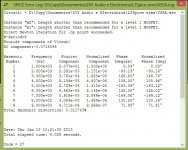
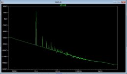
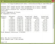
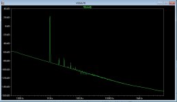
@nikoskey: I posted several test results earlier in this thread, including this one, w. 500KHz sq. wave:I feel that LC showed some post a waveform as result to 500 KHz, but I can not find her..
Square Wave, 20 - 500KHz
This was with 47pF comp capacitors, and with no Zobel installed. It is one of three consecutive posts with some test results and scope pics.
For anyone else: please not that I smoked a Zobel resistor, and possibly some transistors yesterday when I intentionally let the circuit oscillate... (I don't mean to say it is unstable with any reasonable wiring!)
I guess this is what they mean when they say you can't make an omelet without a few broken transistors... 😀
Lazy Cat has the post w. the square wave results in the VSSA thread, not here.
Wow, 12db difference! Am I reading that right? (I will take a closer look later). Thanks!I attached the sim files. The models I use are the Cordell models.
But I simulated with LTSpice both cases and the KSA's give me much lower THD. So, wich ones should I use?
Thanks.
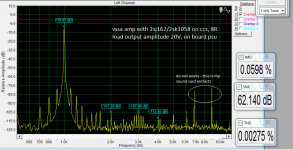
I use KSA/KSC having 155-175 hFE and 5,6 pF Miller cap, 2,7 Mhz (-3 dB) with input filter and Zobel in action, now imagine. 😎
@PMI, I cannot make it oscillate even with 1 m antenna at the input, it just shows strong 47 kHz of Tek LCD. 😀
Wow, 12db difference! Am I reading that right? (I will take a closer look later). Thanks!
KSA/KSC rules
U R da Cat!@PMI, I cannot make it oscillate even with 1 m antenna at the input, it just shows strong 47 kHz of Tek LCD. 😀
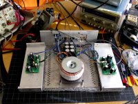
I had a bit more than 1 m, probably double that, the ground was disconnected from the chassis at the time, and one ground lead was intentionally looped about 270 degrees around an unshielded transformer.
I promise to treat your "children" with more respect, 😉
edit: this was about how the test setup looked
Attachments
Last edited:

more output stage for more power
Hello, anyone can help?, how to add next 1 pair output stage for more power output?
thanks, just newbie still learning
Hello, anyone can help?, how to add next 1 pair output stage for more power output?
thanks, just newbie still learning
Hello, anyone can help?, how to add next 1 pair output stage for more power output?
thanks, just newbie still learning
Hi g.y.w.

Welcome to the thread.
There is a two-pair output peeceebee cooking in my kitchen. It will be published in July 1st week. In the meantime you may gather more info on the amp that we all here are fans of. 😀
In case you want to design your own PCB, all you need to do to each FET pair(same polarity) is to short their pins. 1)Drains directly, 2)gates through 100R, 3)sources through 0.1R.
shaan
@Paulo: The tests being discussed here have to do with performance well above normal audio range. If you basically want to experiment with high frequency signals, this is great experience, not to mention fun. If you want a working amplifier to listen to... maybe not so much 🙄
If you have them use the Fairchild KSA1381/KSC3503 pair, if not use the faster version of BD139/140. Use the cap. It will not affect how the amplifier sounds, and it may save you some trouble later...
One thing I found today is that if you test with an unconnected/ungrounded signal cable which is long enough, the circuit can be made to oscillate very easily within the bandwidth of the input filter. I let some smoke out of the Zobel in the process, (pretty much expected at roughly 200KHz). Nothing is completely fool proof, I'll use 1W next time... 😀
P.S.: if you can, please post the simulation, I know I would like to see it, and other people might want to see it too.
Sory for small off topic
I am using bd139/140 group 16 with hfe around 200, very easy to match and there are insulated. THD is very low (version without ccs).
I do not know but it may be useful information, the shaans version with 2sj162/sk1058 have some very small noise when I put my ear to speaker, and there is some hum noise if I twist speaker cables (in the amp) or leave very long input cable. Now to the point, the irfp version is dead silent, I am checking supply voltage couple times to make sure the amp is on, even on scope everythink is clean - Is that due to higher Vgs voltage ? Maybe toshiba 2sj201 version with higher vgs would be better ?
Attachments
Last edited:
I think we might need a little more info to comment... 😉 For example, where are the input grounds connected, is there a ground loop breaker resistor separating the negative input terminal from DC common, where do the speaker return wires go, what kind of transformer is being used or what kind of supply, etc...Sory for small off topic
I am using bd139/140 group 16 with hfe around 200, very easy to match and there are insulated. THD is very low (version without ccs).
I do not know but it may be useful information, the shaans version with 2sj162/sk1058 have some very small noise when I put my ear to speaker, and there is some hum noise if I twist speaker cables (in the amp) or leave very long input cable. Now to the point, the irfp version is dead silent, I am checking supply voltage couple times to make sure the amp is on, even on scope everythink is clean - Is that due to higher Vgs voltage ? Maybe toshiba 2sj201 version with higher vgs would be better ?
Hum noise would be 60Hz (50 in your case), and if it changes when you move any wires, probably not directly related to choice of transistor or mosfet. A harsher buzzing noise is likely to be 120 (100 in Europe), related to the switching in the rectifier diodes.
Any input wire loop, or even a partial loop near the transformer is likely to pick up some 50/60 Hz mains noise. That will happen in my chassis, depending on the position of the transformer and various wires relative to each other. Simple test - if you hold one of the input wires about 2-3 cm above the transformer, does the noise get louder, or not? Does it change frequency or stay the same?
Even if there is no obvious loop, the ground (negative) wires in the input cables can form a kind of ground loop, when the grounds meet at the power supply or at the star ground. If your transformer happens to be in the middle of the loop, or close, some of the noise will be amplified, and show up at the output. That will happen if you have a toroid transformer at center back, and a linear supply center front, with two amplifier boards on either side of the chassis.
I experimented with both center front and center back transformer mounting, and center front makes it easier to eliminate the inductive mains noise pickup in a small chassis. (mine is intentionally about 3/4 of full size.
Rectifier noise on diode switch-off is harder to get rid of. A snubber helps with larger transformers, but after that, you have to filter it out in the power supply. Schottky diodes in the rectifier bridge can help too, because they have close to zero switch-off time, but sometimes they can make things worse for other reasons.
Aside from all that, and back on topic, I would look forward to a discussion of which transistors or mosfets seem to work better ... 😀 At the moment, I am unsure how important matching hfe is in this amp, or how much difference fast transistors in the VAS are going to make at audio frequencies...

I had the 10r/100nf ground separating resistor and It would help but not much.
This is vssa variant with pcb that I do not have any noise problems, not even I put transformer on the amp (or this is the ccs on board result I do not know).
http://www.diyaudio.com/forums/solid-state/237219-fet-hex-explendit-amplifier.html
The board I had the problem with was as it is bellow. After I un-twisted the speaker cables wires (thx LC) problem is gone. I am not sure if puttung big ground pads around the board helps, in my recent pcb I am using very little copper on board and didnt noticed any problems. Maybe my board design was bad.
At the moment I am preparing another one with no ground spreaded all over the place (as before) and I will report the result.
In my case I think It was not problem with ground loop but problem that amp was very sensitive for electromagnetics twisted cables etc.
- Home
- Amplifiers
- Solid State
- PeeCeeBee