also, is it normal offset 0.5v before trimming? some vas pairs give me this high offset, even as high as 0.8v!
Hi,
@shaan, One of my friends had posted on the other forum for PCB's.
Am waiting for the update from you to take things forward,Whats the staus of PCB ?? has it arrived ? Please update here as well.
Regards.
@shaan, One of my friends had posted on the other forum for PCB's.
Am waiting for the update from you to take things forward,Whats the staus of PCB ?? has it arrived ? Please update here as well.
Regards.
Hi SG!
The V1.1 and V2 boards will arrive Monday! ^^ Getting 50s of each.
V3 has been delayed by a week and will probably arrive after 20th.
Thanks.
The V1.1 and V2 boards will arrive Monday! ^^ Getting 50s of each.
V3 has been delayed by a week and will probably arrive after 20th.
Thanks.
Hi shaan ,is on your plan to share new version, v1,1&v2.?Hi SG!
The V1.1 and V2 boards will arrive Monday! ^^ Getting 50s of each.
V3 has been delayed by a week and will probably arrive after 20th.
Thanks.
Hi thimios.
All three versions will be shared with layout, silkscreen and mask as soon as I get the printed boards at hand.

All three versions will be shared with layout, silkscreen and mask as soon as I get the printed boards at hand.
Hi thimios.
All three versions will be shared with layout, silkscreen and mask as soon as I get the printed boards at hand.
Ok thanks🙂
thanks shaan, but how about... 1.8v after hours of playing? :-0
- can i measure and trim without a load connected?
- do vas transistors need a heatsink in order to lessen the drift?
- can i measure and trim without a load connected?
- do vas transistors need a heatsink in order to lessen the drift?
thanks shaan, but how about... 1.8v after hours of playing? :-0
Did you trim it to zero at start? It may need a zobel.
can i measure and trim without a load connected?
Yes. But it may need a zobel. Oscillations can make your meter go loopy.
do vas transistors need a heatsink in order to lessen the drift?
I can's say for sure that it will help reduce drift but a couple small heatsinks is always a good idea.
Hi,
Thanks for the update @shaan. Will look forward to the same. V2 is the one with 2pairs of output right ?
Can you please get the PSU boards made as well along with the protection ?? I myself can take 10 odd boards of each,So Am sure there will be others who'd want them just as me.Please do look into it and try and make it happen.
Regards.
Hi SG!
The V1.1 and V2 boards will arrive Monday! ^^ Getting 50s of each.
Thanks for the update @shaan. Will look forward to the same. V2 is the one with 2pairs of output right ?
Can you please get the PSU boards made as well along with the protection ?? I myself can take 10 odd boards of each,So Am sure there will be others who'd want them just as me.Please do look into it and try and make it happen.
Regards.
Hi SG.
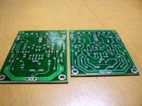
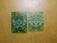
Yes V2 is the dual-FET one. The input cap has been omitted in all three versions btw.
I have prepared a simple PS board that that will have TO220 diode bridge, 2x 10000uF 1.2" diameter caps and 1x 0.1uF per rail, bleeder resistor, 2x supply headers per rail and 4x ground headers on 70micron copper. It doesn't have a speaker protection, yet. 😉 Learning how to implement one. 😀
There seems a load of dedicated speaker protection boards available on the net, mostly 1237 based. Do you think these are good?
i think the vas i used were partially damaged. can bd transistors still function even with a damage that shows off as a high offset that i'm getting? i do get pops, crackles but the sound they make is normal. and yes, zobel is installed..
Hi donovas.
Does the offset move when you try to trim?
BJTs usually show weird behavior if not fully dead or alive.
Does the offset move when you try to trim?
BJTs usually show weird behavior if not fully dead or alive.
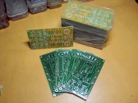
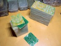
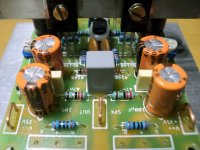
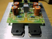
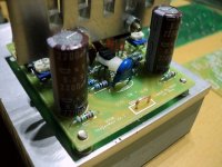
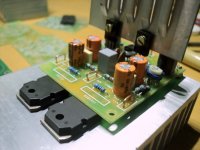
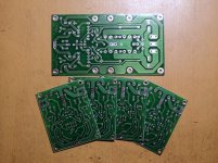
And here we go! 😎
V1.1 and V2 reach home this morning!!! 😀
V1.1 and V2 reach home this morning!!! 😀
Attachments
-
 DSC05128.JPG345.6 KB · Views: 699
 -
 DSC05141.JPG299.8 KB · Views: 269
 -
 DSC05140.JPG295.3 KB · Views: 262
 -
 DSC05139.JPG273.5 KB · Views: 291
 -
 DSC05138.JPG266.4 KB · Views: 320
 -
 DSC05137.JPG242.5 KB · Views: 324
 -
 DSC05136.JPG208 KB · Views: 605
 -
 DSC05134.JPG240.2 KB · Views: 629
 -
 DSC05133.JPG200.7 KB · Views: 656
 -
 DSC05125.JPG261.1 KB · Views: 676
Hi shaan can I get pcb from you? What will be price?
Regards.
Hi shaan, I too would like to get a pair, the double fet version.
Reg
Prasi
Last edited:
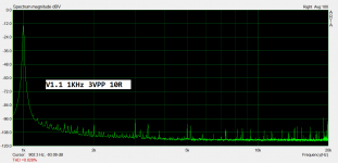
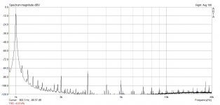
Some measurements of the V1.1 PeeCeeBee. Measured after an 11:1 attenuation from the resistive load.
Pic 1 - 3VPP into 10R.
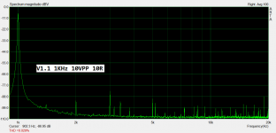
Pic 2 - 10VPP into 10R.
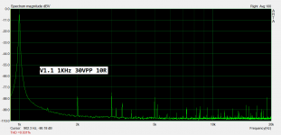
Pic 3 - 30VPP into 10R.
Pic 4 - Residual distortion of soundcard output.
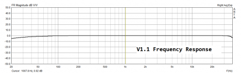
Pic 5 - Freq. Response from 20Hz to 40KHz.
Notice the first three pics. THD reading showing nearly static distortion of 0.03%. Also notice the noise floor. Now, my PCs 1KHz residual distortion is about 0.014% shown in pic 4. So you do the math. 😉
The cutoff slopes in the freq. response trace is due to my sound-card's internal LF response and sampling rate limit.
Coming next - clipping and slew performance.
Pic 1 - 3VPP into 10R.
Pic 2 - 10VPP into 10R.
Pic 3 - 30VPP into 10R.
Pic 4 - Residual distortion of soundcard output.
Pic 5 - Freq. Response from 20Hz to 40KHz.
Notice the first three pics. THD reading showing nearly static distortion of 0.03%. Also notice the noise floor. Now, my PCs 1KHz residual distortion is about 0.014% shown in pic 4. So you do the math. 😉
The cutoff slopes in the freq. response trace is due to my sound-card's internal LF response and sampling rate limit.
Coming next - clipping and slew performance.
Attachments
- Home
- Amplifiers
- Solid State
- PeeCeeBee