Thanks again John .
Has anyone test with these fets. 2SK1530 & 2SJ201?
Thanks.
Many thank to you. I will do follow your comments
No, but very similar.Hi PMI very good results!
Is this from version of page ?http://www.diyaudio.com/forums/solid-state/231662-peeceebee-40.html#post3490152
post#393?
Regards.
Thimios.
You have a very different board now, with two output pairs. So it is difficult to give advice when I have not tried it. My guess would be to try the 100pF.Hi Pete, I wish I have a scope too...🙄🙄
Can you try it with higher than 47pF or lower than that...
that might very interesting to know, by me at least 😀
I use 33pF by now (was 22pF)I plan on trying lower, 22~24pFd

Last edited:
peeceebee

Waiting for this pdf!
just now i see this.http://www.diyaudio.com/forums/solid-state/244903-another-through-hole-vssa-build-thread.html
Good luck at this new travel.
Ok SirYes, 🙂
Waiting for this pdf!
just now i see this.http://www.diyaudio.com/forums/solid-state/244903-another-through-hole-vssa-build-thread.html
Good luck at this new travel.
Last edited:
Will try
So I will try my newest PeeCeeBee... http://www.diyaudio.com/forums/solid-state/231662-peeceebee-136.html#post3669805
this is the simplest one I think
I hope can made it soon, comparison is waiting 😀
So I will try my newest PeeCeeBee... http://www.diyaudio.com/forums/solid-state/231662-peeceebee-136.html#post3669805
this is the simplest one I think
I hope can made it soon, comparison is waiting 😀
Attachments
Last edited:
vssa
Waiting results!One day latter 🙂
will share the pdf when it is tested
Nice job! Are you building these from the original schematic in this thread?...
I hope can made it soon, comparison is waiting 😀
Hi Pete, I'm planning build the another through hole version tooNice job! Are you building these from the original schematic in this thread?
with more parts count 😀
Yes, it is basic Shann's PeeCeeBee and only additional caps 22pF on vas
68 ohm on J162's gate, 15k offset now with series trimmer so it is so easy to zero the offset.
I will post the BoM that I use, with alternatives substitution.
Also it is nice idea to post schematic with value, I will take Shaan schematic & add the missing value & I hope he doesn't mind 🙂
(where is Shaan btw ? anyone knows?)
I have quick test them & the offset is low but not connected to speakers yet
cos I know it is all fine 😎
(need some flux cleaning)
Tomorrow it will sing I guess 😀 now is late night here
Regards
One day latter 🙂
will share the pdf when it is tested
John , Id really like to give it a try!
Tell us how it sounds? 🙂
One day latter 🙂
will share the pdf when it is tested
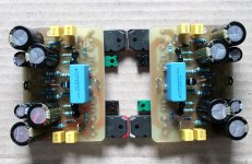
Power is nice and I like the symmetrical arrangement.
incredible
One day latter 🙂
will share the pdf when it is tested
hi john,
i'm going to build your second pcb iteration.
this time with premium parts too. 🙂
vssa
Hi John
What about first fire?
Waiting for pcb pdf!
My silicon chip 20W class A is already speaking!
Hi Pete, I'm planning build the another through hole version too
with more parts count 😀
Yes, it is basic Shann's PeeCeeBee and only additional caps 22pF on vas
68 ohm on J162's gate, 15k offset now with series trimmer so it is so easy to zero the offset.
I will post the BoM that I use, with alternatives substitution.
Also it is nice idea to post schematic with value, I will take Shaan schematic & add the missing value & I hope he doesn't mind 🙂
(where is Shaan btw ? anyone knows?)
I have quick test them & the offset is low but not connected to speakers yet
cos I know it is all fine 😎
(need some flux cleaning)
Tomorrow it will sing I guess 😀 now is late night here
Regards
Hi John
What about first fire?
Waiting for pcb pdf!
My silicon chip 20W class A is already speaking!
Last edited:
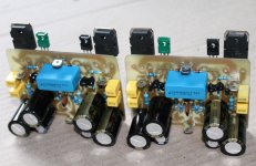
Ok, teasted 🙂
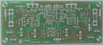
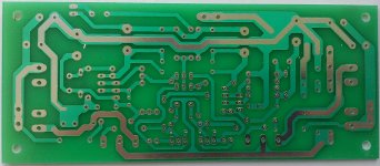
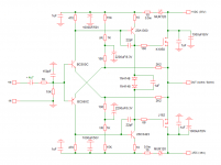
Hi, this PeeCeeBee has been tested...
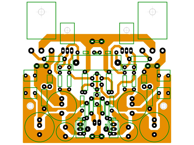
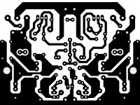
This is the schematic with value, the top & also bottom layout.
PeeCeeBee size is 80 x 60 mm 🙂
The input cap is out the board 😀 , choose your favorite.
The optimal bias for the Latfet is 160mA + 10mA for VAS + less than 3mA for input pair so if total 175mA current for one channel it is good...
Today I power it up with +/-35VDC, with only 15k resistor I got 200mA total current.
So it is about 176mA quiescent current, this make them hot...
So I try measure at 10 ohm VAS transistor shows 230mV = 23mA for the transistor & it is not good (too much current).
Then I lower the voltage at +/-32VDC & I have better feeling on this 🙂
Total current is 177mA
Bias = 161mA
VAS = 13mA
At 15k resistor is optimal at +/-32VDC (for my set up)
maybe you get another measurement.
Then I put the two 1k trimmer, now it so easy to get zero offset.
When the offset is negative turn the positive side trimmer(increase value) to make zero offset. I'm play with this, try to decrease one 1k & increase another got 99mV offset
With 16k "offset" resistor & +/-35VDC
Bias = 174mA
VAS = 18mA
So I need more than 16k if I use +/-35VDC to make it optimal.
Enough for now,
I thing somebody want to make this PeeCeeBee too...
please enjoy & let me know if it is not work on your building
About the sound it is PeeCeeBee sound 🙂, not connected to my big speakers yet 😀
I thought my previous one sounds better, this one is good too but I feel something is missing.
I start to think the capacitor effect, I don't make a re-forming for the 2200uF caps (maybe I should try to replace them)
I try different caps here but I still have like the one I used before.
Also I add cheap input capacitor, this could be make the sound feel different.
Please take a good quality one at the input caps & don't make it direct coupled.
Regards
Hi, this PeeCeeBee has been tested...
This is the schematic with value, the top & also bottom layout.
PeeCeeBee size is 80 x 60 mm 🙂
The input cap is out the board 😀 , choose your favorite.
The optimal bias for the Latfet is 160mA + 10mA for VAS + less than 3mA for input pair so if total 175mA current for one channel it is good...
Today I power it up with +/-35VDC, with only 15k resistor I got 200mA total current.
So it is about 176mA quiescent current, this make them hot...
So I try measure at 10 ohm VAS transistor shows 230mV = 23mA for the transistor & it is not good (too much current).
Then I lower the voltage at +/-32VDC & I have better feeling on this 🙂
Total current is 177mA
Bias = 161mA
VAS = 13mA
At 15k resistor is optimal at +/-32VDC (for my set up)
maybe you get another measurement.
Then I put the two 1k trimmer, now it so easy to get zero offset.
When the offset is negative turn the positive side trimmer(increase value) to make zero offset. I'm play with this, try to decrease one 1k & increase another got 99mV offset
With 16k "offset" resistor & +/-35VDC
Bias = 174mA
VAS = 18mA
So I need more than 16k if I use +/-35VDC to make it optimal.
Enough for now,
I thing somebody want to make this PeeCeeBee too...
please enjoy & let me know if it is not work on your building
About the sound it is PeeCeeBee sound 🙂, not connected to my big speakers yet 😀
I thought my previous one sounds better, this one is good too but I feel something is missing.
I start to think the capacitor effect, I don't make a re-forming for the 2200uF caps (maybe I should try to replace them)
I try different caps here but I still have like the one I used before.
Also I add cheap input capacitor, this could be make the sound feel different.
Please take a good quality one at the input caps & don't make it direct coupled.
Regards
Attachments
Last edited:
- Home
- Amplifiers
- Solid State
- PeeCeeBee