You must find one, I ordered it online from local friend 🙂Thans john.
My next project?
Maybe but i haven't fets...
& make sure they are lateral mosfet. K1058-J162 I think they should be available almost everywhere but sometimes we don't know where to buy, until someone told us 😱.
Yes, this must be built.
the sound of six transistors magic is waiting for you & I still prefer this one than any other amps.
For powering up you also can see post #431http://www.diyaudio.com/forums/solid-state/231662-peeceebee-44.html#post3493837
I use bulb tester BTW 🙂
Regards
Last edited:
Very useful John, and close to my own measurements.With 16k "offset" resistor & +/-35VDC
Bias = 174mA
VAS = 18mA
So I need more than 16k if I use +/-35VDC to make it optimal.
LC recommended 12 mA VAS bias, and 160 mA total bias, measured over a 22 ohm resistor in series with the supply. This was with the ALFET, not the Renesas 2SK1058/2SJ162. It was also with the VAS transistors on the main heatsink, where they stay cooler. As the VAS temperature goes up, so does the VAS current.
So, with VAS top-side, my measurements are about this:
Supply: +/-45V
Input pair: 1.9
VAS: 17.3 (after coming to stable temp, ~43C)
Total: 160 (total, means including VAS and Input)
Supply: +/-35V
Input: 2.1
VAS: 18.9
Total: 162
Note that at lower supply voltage higher front end bias required to reach 160 ma total idle current (0.2 mA is a significant difference in this case)
When changing supply voltage with bias settings fixed, (CCS helping to keep front end bias stable) I get the following:
Supp/Inp/VAS/Tot
25V 1.89 11.6 140
30V 1.90 13.2 144
35V 1.91 14.2 151
40V 1.92 14.8 154
45V 1.92 17.3 160
During this test, main heatsink temperature rises only slightly. The little VAS heatsink gets progressively hotter.
So you can see the trend. As the supply voltage is raised, the VAS dissipates more power with the same input bias setting, and the VAS current rises. (VAS BJT has a positive temperature coefficient).
So, with each increase in supply voltage, you should calibrate to a lower VAS current to achieve the same result, and to prevent the VAS from overheating.
edit:
These were measurements taken with my latest board, the results with the previous one were similar, but a bit harder to interpret, because the current and temp readings were less stable.
Last edited:
Hi, Pete,Very useful John, and close to my own measurements.
.....
So, with each increase in supply voltage, you should calibrate to a lower VAS current to achieve the same result, and to prevent the VAS from overheating.
.
Your explanation is better 🙂 ...
& that underlines is something I'm searching for ...
how to achieve it ... 🙄
the 160mA bias I thought only for the LatFet (K1058-J162) 😀
I'm also thinking a very simple resistor + LED's(or zener) combination CCS
& without j-fet or other two transistors
to still keep it 6 transistors magic
Regards
Last edited:
I don't think I know enough to take sides in the pro-CCS anti-CCS discussion. There are some interesting posts in the main VSSA thread though. CRD (constant current diode) was discussed, for example.... I'm also thinking a very simple resistor + LED's(or zener) combination CCS
& without j-fet or other two transistors
to still keep it 6 transistors magic
I can confirm that Shaan's version sounds excellent without CCS, especially if the power supply is very good. This means a highly filtered supply, like a bench supply, or a big CRC filter, etc. I still listen to my version of his original circuit almost every day. The need for a clean supply is how I came across the Cap Multiplier version by Mr Evil.
Ok,. no CCS here...
Keep it simple, my first PeeCeeBee for stereo only use 4 x 6800uF/50v + 1 x bridge diode + 1 x transformer 25VCT..
It is simple power supply not a CRC or any multiplier.
I also use under ratted transformer & sometimes play hard enough.
And you know it is soft clipping, ...
The sound is still so good with that poor power supply...
some people don't even believe it is only 50w amp, why it so clear & loud 🙂
I must try to compare it with my 10.000uF x 6 CRC power supply 🙂
or make a regulated power supply or caps multiplier too...
What I posted about the bias current applies regardless of how it is adjusted, as long as the bias is stable, this will apply as the supply voltage is increased.Ok,. no CCS here...
Keep it simple, my first PeeCeeBee for stereo only use 4 x 6800uF/50v + 1 x bridge diode + 1 x transformer 25VCT..
It is simple power supply not a CRC or any multiplier.
I also use under ratted transformer & sometimes play hard enough.
And you know it is soft clipping, ...
The sound is still so good with that poor power supply...
some people don't even believe it is only 50w amp, why it so clear & loud 🙂
I must try to compare it with my 10.000uF x 6 CRC power supply 🙂
or make a regulated power supply or caps multiplier too...
Clipping behavior and hf response is excellent, I will try to post some pics, but I am short on time today.
People often compensate for lower sound quality by more power (like in a car, for example). This is what our instinct tells us - if you want to hear better, turn up the volume. It is a trick played by our mind. So, when the sound is very good, people will often assume that the amplifier is at a much higher power level.
Of course, having efficient speakers also helps. If you have speakers that need a lot of power, 50W is not enough. With efficient speakers, and 50W per channel, you can drive your neighbors out of their house... 😉
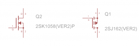
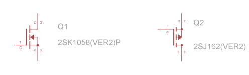
I could not find eagle library files for 2sk1058/2sj162,so i made some of my own.
They have been bodged together from different libraries,so are not exact.
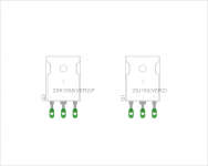
The main thing that got my goat was that eagle has no TO-3P packages like the ones the latfets come in.So,i had to use TO-3P packages from another model.But the packages say that they are TO-3P,and when i overlaid them on the TO-3P of the Hitachis,they look to be only a wee bit more bigger.
I have attached the files,so could anyone please check them for me?
The images show how the symbol looks and how the final package is.I guess they are ok?
To all those who draw their own boards,especially John Bali,what do you use to draw the tracks?Permanent marker?
I have a marker which says "Permanent OHP Marker",with a fine tip.anything i draw on a pcb gets washed away during etching due to heat leaving nothing on the board.
They have been bodged together from different libraries,so are not exact.
The main thing that got my goat was that eagle has no TO-3P packages like the ones the latfets come in.So,i had to use TO-3P packages from another model.But the packages say that they are TO-3P,and when i overlaid them on the TO-3P of the Hitachis,they look to be only a wee bit more bigger.
I have attached the files,so could anyone please check them for me?
The images show how the symbol looks and how the final package is.I guess they are ok?
To all those who draw their own boards,especially John Bali,what do you use to draw the tracks?Permanent marker?
I have a marker which says "Permanent OHP Marker",with a fine tip.anything i draw on a pcb gets washed away during etching due to heat leaving nothing on the board.
Attachments
Hi, this PeeCeeBee has been tested...
This is the schematic with value, the top & also bottom layout.
PeeCeeBee size is 80 x 60 mm 🙂
...
Regards
Thank you John!
Off to collect parts...
The main thing that got my goat was that eagle has no TO-3P packages like the ones the latfets come in.So,i had to use TO-3P packages from another model.But the packages say that they are TO-3P,and when i overlaid them on the TO-3P of the Hitachis,they look to be only a wee bit more bigger.
I have attached the files,so could anyone please check them for me?
The images show how the symbol looks and how the final package is.I guess they are ok?
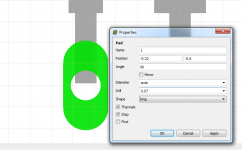
Make holes a little bit bigger and you can fit all Latfets including Exicons, Magnatecs and Alfets. These have somewhat wider pins than Renesas. Make holes 1,5mm.
Yes permanent marker can be used, the big one for better result.To all those who draw their own boards,especially John Bali,what do you use to draw the tracks?Permanent marker?
I have a marker which says "Permanent OHP Marker",with a fine tip.anything i draw on a pcb gets washed away during etching due to heat leaving nothing on the board.
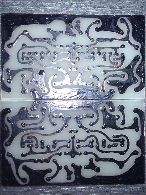
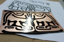
With fine tip the ink is not thick enough & they will washed away. 😀 three layer lines draw with fine tip will do fine but single line big permanent marker will be better.
Don't worry to use bigger marker I design with enough clearance so I can still draw it manually. If you draw wrong line or pad use a sharp knife or similar to erase it.
Before used refill the ink in the permanent marker to make something like this:
Please, see post #401 my first PeeCeeBee :
Here a video how to hand made PCB Hand Drawing PCB - YouTube this is the power supply board.
The PeeCeeBee will took a longer video so I don't make the video 🙂
The attached picture will show you how thick from two layer big permanent is done.
Regards
Attachments
The holes are 1.5mm,already,1.6 to be exact.Make holes a little bit bigger and you can fit all Latfets including Exicons, Magnatecs and Alfets. These have somewhat wider pins than Renesas. Make holes 1,5mm.
However,i find locally made through hole plated boards have a reduced diameter compared to the original due to shoddy plating,i raised the drill holes to about 1.8mm diameter.
I havent tested them yet,my only pair of latfets are already on another board.
Yes permanent marker can be used, the big one for better result.
With fine tip the ink is not thick enough & they will washed away. 😀 three layer lines draw with fine tip will do fine but single line big permanent marker will be better.
Don't worry to use bigger marker I design with enough clearance so I can still draw it manually. If you draw wrong line or pad use a sharp knife or similar to erase it.
Before used refill the ink in the permanent marker to make something like this:
Please, see post #401 my first PeeCeeBee :
Here a video how to hand made PCB Hand Drawing PCB - YouTube this is the power supply board.
The PeeCeeBee will took a longer video so I don't make the video 🙂
The attached picture will show you how thick from two layer big permanent is done.
I see!Thanks!
Attachments
Last edited:
Hi John,Hi Pete, ...
Can you try it with higher than 47pF or lower than that...
that might very interesting to know, by me at least 😀
I use 33pF by now (was 22pF)...
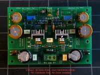
This weekend I finished most of my testing, up to +/-45V supply. Some results with alternative components incl. 22pf compensations caps...:
BC546C/BC556C input
KSA1381E/KSC3503E VAS
1W feedback resistor, and a few other small changes
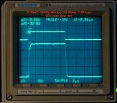
To answer your earlier question, this board is a little faster w. 22pF caps (higher slew rate), and the output observed running higher frequency square waves is a bit more symmetrical.
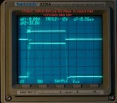
Overall no big change, and no problems were observed. No sign of oscillation, instability, or overshoot. Improvements are slight, not enough to warrant changing the parts recommended so far, but I was excited to see >100 KHz slew rate with no instability.
Actual slew rate calculation was 120V/usec with no load, and ~90V/usec with 7.5R resistive load. Test was run with +/- 35V supply, 50KHz 40V pk-to-pk square wave.
No more testing for a few days, need to catch up on other things... 😀
Attachments

Hi Pete, +/-45VDC to have 40V pk-to-pk right?Hi John,
This weekend I finished most of my testing, up to +/-45V supply. Some results with alternative components incl. 22pf compensations caps...:
BC546C/BC556C input
KSA1381E/KSC3503E VAS
1W feedback resistor, and a few other small changes
To answer your earlier question, ....
Actual slew rate calculation was 120V/usec with no load, and ~90V/usec with 7.5R resistive load. Test was run with +/- 35V supply, 50KHz 40V pk-to-pk square wave.
No more testing for a few days, need to catch up on other things... 😀
& yes I'm waiting that other things 😀
Btw, thanks for trying that cap value.
so it is safe with 22pF with your board
my latest PeeCeeBee also use 22pF 😀
I will say +/-40VDC maximum when use my board
(not tested yet with +/-45VDC)
& don't go up more than +/-35VDC if the VAS are BD139-140
(risk of burning some 10 ohm resistor)
Regards
Yes, +/- 45V will clip around 41~42V, so 100 watt/channel. I think "safe" will depend on the selection of components, not so much on my board?Hi Pete, +/-45VDC to have 40V pk-to-pk right?
& yes I'm waiting that other things 😀
Btw, thanks for trying that cap value.
so it is safe with 22pF with your board
my latest PeeCeeBee also use 22pF 😀
I will say +/-40VDC maximum when use my board
(not tested yet with +/-45VDC)
& don't go up more than +/-35VDC if the VAS are BD139-140
(risk of burning some 10 ohm resistor)
Regards
Hey guys. 
How are you?
Due to other important things that I can't ignore I am currently angry with myself that I can't find enough time to have and share the fun. But congrats and cheers to everyone who posted here and made this thread a common place for activity, positivity and creativity among PeeCeeBee lovers.
Thanks to all and happy listening.
shaan
We've been hangin out on Pete's thread recently because he has just been getting his new boards out to people. Once I get home from vacation, I will be finishing the case for my TO-3 peeceebee. Looking forward to having it in the amp stack as as well as Pete's version.
Hello everybody !
Are you all drowsy ! What happens ?
I suspect everyone is too busy merrily listening to their PeeCeeBees.
First, I would like to thank Lazy Cat and Shaan for an outstanding design, ...
PDF Files attached, as requested, including silk screen, bottom copper, silkscreen and bottom copper overlapped, with heatsink location shown in green. The files are 1:1 scale (100%). Dimensions are 102x64mm (approximately 4x2.5, 10 inches square). My BOM is also attached.
...
Hi PMI,
I would like, if possible, to see YOUR schematic for this bord which I'm interested with to etch myself.
Regards
Michel
- Home
- Amplifiers
- Solid State
- PeeCeeBee