Do you mean the loop breaker circuit? Just to be clear, it's OK to connect the ground from the PSU to the earth safety on the chassis? I got the information regarding using a separate connection to the chassis for the PSU ground from figure 2 on Rod Elliot's site: Power Supply Wiring Guidelines
Fig 4 in this page: Earthing (Grounding) Your Hi-Fi - Tricks and Techniques
See also Fig 8 here:
Mains DC and Transformers
Image attached as it wasn't included in the last post. I've also updated it to include the connection of the IEC earth to chassis ground as per Loafimus's suggestion.
Does it all look correct now?
I would put your RCA grounds going to PSU ground and not the chassis. I would go from PSU ground to chassis ground and put a CL-60 between PSU and chassis. This is to separate your audio ground from your dirty chassis ground, but have it available in case it's needed.
http://hifisonix.com/wordpress/wp-content/uploads/2018/07/How-to-wire-up-an-amplifier_3.pdf
There's a ton of good information in that presentation, which is what I used.
IEC earth to chassis earth. I did some reading on this, both on this forum and links provided and came away none the wiser really. I read in a few places that the IEC earth should be fixed to the chassis and that it should be the only thing connected at that point (in my chipamp I had the chassis ground connected to the earth). That's why I put the chassis ground from the PSU on a separate connection. I don't understand the rationale behind this if they're both connected to the chassis though. This aspect just confuses me.
This is explained also in that presentation. From my understanding, you only want one chassis ground point to prevent ground loops.
Last edited:
Fig 4 in this page: Earthing (Grounding) Your Hi-Fi - Tricks and Techniques
See also Fig 8 here:
Mains DC and Transformers
Thanks, just checking we were talking about the same thing. I have read these again and understand it now. There is a PCB for the ground lifter as described by Rod Elliott in this article, part way down the page A Complete Guide to Design and Build a Hi-Fi LM3886 Amplifier - Circuit Basics
I've just priced it up and it's £6 for 10 so I'll order them.
I would put your RCA grounds going to PSU ground and not the chassis. I would go from PSU ground to chassis ground and put a CL-60 between PSU and chassis. This is to separate your audio ground from your dirty chassis ground, but have it available in case it's needed.
http://hifisonix.com/wordpress/wp-content/uploads/2018/07/How-to-wire-up-an-amplifier_3.pdf
There's a ton of good information in that presentation, which is what I used.
This is explained also in that presentation. From my understanding, you only want one chassis ground point to prevent ground loops.
Thanks again for your input. I have read that and am understanding it a bit more now with everybody's help. I did note though that it has a different way of wiring the ground lift compared to Rod Elliotts in the earthing article(see attached image).
Again, many thanks to everyone for their help and patience, it's been a bit of a steep learning curve for me working on this amp.
Attachments

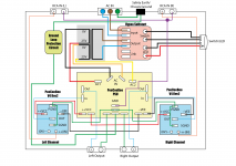
I've made what I think is my final layout block diagram, so thanks to Loafimus, JLS001 and of course Shaan for helping me along.
On the diagram, I've connected the RCA input grounds together and routed these to PSU GND, which then exits the PSU through a ground loop protection circuit before connecting to the chassis at safety earth.
I have a further question regarding this layout. If the RCA input grounds go to the PSU GND, what is the point in having the --0V input (gnd) on the amp? It's not meant as criticism, I just don't understand.
Cheers
Neal
Attachments
... If the RCA input grounds go to the PSU GND, what is the point in having the --0V input (gnd) on the amp? It's not meant as criticism, I just don't understand.
Cheers
Neal
The 0V at input is signal ground. The shield of the input cable is supposed to connect to it. In case there is a ground loop problem in a stereo installation, this technique of leaving 0V unconnected and shorting the shields and routing directly to ground can help lower the noise. In dual mono and monoblock setup this technique is not necessary as the two channel do not share the grounds except at the signal source and a local induction loop can not form in the input shield between the two channels.
One has to keep in mind that as long as a shared ground is used with or without breakers, there will be a local induction loop as soon as the far end of the input cable shields touch one another (which is normally the case when a source is connected). This loop is different from the typical GND loop that happens through mains earth when source and amp share the same mains earth without any breakers. It is also one of the oldest problems in stereo amplifiers sharing one PSU. The noise it injects into the input depends directly on transformer's leakage EMI and distance of the loop from transformer. It can also be frustrating at times; I have seen chipamps where there is hum from speakers when the two input RCA far ends are not touching, and as soon as they are touching the amp goes into pin drop silence, and no there is no loose connection!
As Asuslover put adequately, grounding is definitely more complicated than anyone would like it to be.
More help needed I'm afraid.
I've got one channel working fine, no problems and very straightforward, all biased, runs well and had music coming through the test speaker ok.
Started on the second channel today and it's not happy. Smoke from resistors R9 and R10.
I've checked for obvious faults including:
I've got one channel working fine, no problems and very straightforward, all biased, runs well and had music coming through the test speaker ok.
Started on the second channel today and it's not happy. Smoke from resistors R9 and R10.
I've checked for obvious faults including:
- All capacitors are correct for polarity
- All diodes are correct for polarity
- The small transistors are correct in orientation and placement
- BD139 (Q10) and B140 (Q9) are correct
- 2SK (Q11) and 2SJ (Q12) are correct
It looked like there was a short on the BD140, so I replaced that and the two resistors, but the same happened again, both R9 and R10 smoked with the 1 second test.
Hi Neal.
Check the small signal BJTs and BDs for base-collector and base-emitter diode drop. A short at the BDs can lead to death of Q3/Q4.
Check the small signal BJTs and BDs for base-collector and base-emitter diode drop. A short at the BDs can lead to death of Q3/Q4.
Hi Neal.
Check the small signal BJTs and BDs for base-collector and base-emitter diode drop. A short at the BDs can lead to death of Q3/Q4.
Thanks for getting back to me Shaan. I have a day off tomorrow and luckily some spare BJTs and BDs, so I can test and hopefully rebuild it then.
I have a V4 already built since more than 1year ago. where can i find the list of upgrades in order to take it to Rev2?
What advantages bring Rev2 sonically?
What advantages bring Rev2 sonically?
Last edited:
Hi Neal.
Check the small signal BJTs and BDs for base-collector and base-emitter diode drop. A short at the BDs can lead to death of Q3/Q4.
Sadly, no good still.
I've replaced Q3 and Q4 and the BDs. Q5 and Q6 measured differently to all the others as well so I replaced those, just in case and the two burnt resistors. The amp powers up ok now but there's no voltage across R26.
I have a V4 already built since more than 1year ago. where can i find the list of upgrades in order to take it to Rev2?
What advantages bring Rev2 sonically?
See post #704 - he gives pictorial step by step
I have it working and playing through my test speaker!
I read back through some of the posts to find other information and came across a difference in setup procedure. If I put the MM probes across R29, everything works right, but from what I can gather, that was for Rev1, Rev2 uses the 47ohm resistors that are connected in parallel. I have a Rev2 board. I realised that this is the same way I set up the other channel.
Is there a problem with the way I've set it up using these resistors? I don't want to connect it to my decent speakers yet, or start building it into the chassis if something is going to go wrong.
Last edited:
See post #704 - he gives pictorial step by step
Thanks for answer, i noticed that post but there is specified is an upgrade from Rev1 to rev2, What are the mods from V4 vanilla and Rev1?
For example i noticed R11/12 from V4 are 22k and V4H same resistors are 33k
Thanks for answer, i noticed that post but there is specified is an upgrade from Rev1 to rev2, What are the mods from V4 vanilla and Rev1?
For example i noticed R11/12 from V4 are 22k and V4H same resistors are 33k
I don’t think you can go V4 orig to V2, you have to ha e the V2 board to start.
You can’t compare values on the V4 to V4H those are different designs
As far as i understand looking on the schematics V4H is a V4 with 2 pairs of output power transistors
As far as i understand looking on the schematics V4H is a V4 with 2 pairs of output power transistors
Yup you are correct, but doesn’t mean the same values are used, so I would stick with the V4 schematic
- Home
- Group Buys
- PeeCeeBee V4 GB!