

So I've clocked nearly five hours of music with the new V4 amp and the sound is changing gradually. On initial power up the sound was big and bold and it was right away apparent that this amp got tonality spot on. Its balance of bass, midrange and highs is also very right. Will update its sonics as it gains more hours.
Hi Shaan,
Just gathering the last few parts for the build. I'm having a bit of trouble finding mica sheets. Would this material be ok for isolating the Mosfets?
https://cpc.farnell.com/bergquist/k10-104/thermal-pad-to-3p/dp/SC10731
I assume the electrical isolation will be fine but I'm unsure about the thermal properties.
Neal
Just gathering the last few parts for the build. I'm having a bit of trouble finding mica sheets. Would this material be ok for isolating the Mosfets?
https://cpc.farnell.com/bergquist/k10-104/thermal-pad-to-3p/dp/SC10731
I assume the electrical isolation will be fine but I'm unsure about the thermal properties.
- Thermal impedance 0.41°C-in2/W (@50 psi)
- 0.2°C/W thermal resistance
Neal
Hi Nealj.
The website is showing offline. Can you post a picture/screenshot of the material? The thermal resistance is fine though.
The website is showing offline. Can you post a picture/screenshot of the material? The thermal resistance is fine though.
Hi Shaan,
Sorry about that, the website kept on going offline yesterday when I was trying to get my order together.

Sorry about that, the website kept on going offline yesterday when I was trying to get my order together.
Hi Shaan,
Financial transactions done
Zacharia
Thanks. You have PM.
Help with wiring
Hi all,
I need some advice about wiring everything up together.
I'm very much a novice and I've largely followed instructions in the past, or have managed to work things out for myself which haven't been explicit, but I'm a little uncertain about putting this amplifier together.
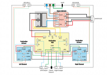
In addition to the V4 Rev2 PCBs, I'm using Shaan's PSU and a Hypex softstart which can also incorporate a vandal proof type LED power switch, which I plan to use. Would somebody please be kind enough to go over my block diagram of the wiring to see if I've made any mistakes? I'm also unsure of where the signal ground from the amp is supposed to connect to.
Any advice much appreciated.
Cheers
Neal
Hi all,
I need some advice about wiring everything up together.
I'm very much a novice and I've largely followed instructions in the past, or have managed to work things out for myself which haven't been explicit, but I'm a little uncertain about putting this amplifier together.
In addition to the V4 Rev2 PCBs, I'm using Shaan's PSU and a Hypex softstart which can also incorporate a vandal proof type LED power switch, which I plan to use. Would somebody please be kind enough to go over my block diagram of the wiring to see if I've made any mistakes? I'm also unsure of where the signal ground from the amp is supposed to connect to.
Any advice much appreciated.
Cheers
Neal
Attachments
Hi all,
I need some advice about wiring everything up together.
I'm very much a novice and I've largely followed instructions in the past, or have managed to work things out for myself which haven't been explicit, but I'm a little uncertain about putting this amplifier together.
In addition to the V4 Rev2 PCBs, I'm using Shaan's PSU and a Hypex softstart which can also incorporate a vandal proof type LED power switch, which I plan to use. Would somebody please be kind enough to go over my block diagram of the wiring to see if I've made any mistakes? I'm also unsure of where the signal ground from the amp is supposed to connect to.
Any advice much appreciated.
Cheers
Neal
Pretty much the same setup I did.
You'll want to put a jumper from SGND to PGND, then from PGND to the GND on the PSU.
Also, your IEC earth should go to Chassis Ground.
I'll be interested to see if you have any hum in your amp wired up like you do in your diagram. I ended up with a bit of hum and the biggest help was tying the two RCA in grounds together. I also added a CL-60 thermistor to split the PSU GND from the chassis GND.
Just a suggestion, but you may also want to add a mains fuse in there before your soft-start.
Hi Loafimus,
Thanks for chipping in.
With regard to the jumper from SGND - how do you do that with just the one tab - do you put two wires into one faston for example?
I have a mains fuse in the IEC connector, but thanks for the check.
IEC earth to chassis earth. I did some reading on this, both on this forum and links provided and came away none the wiser really. I read in a few places that the IEC earth should be fixed to the chassis and that it should be the only thing connected at that point (in my chipamp I had the chassis ground connected to the earth). That's why I put the chassis ground from the PSU on a separate connection. I don't understand the rationale behind this if they're both connected to the chassis though. This aspect just confuses me.
Sorry if this seems a bit basic, but can you explain what you mean by tying the RCA grounds together please? Do you mean running a wire (jumper?) between the tabs of the RCA sockets? What happens at the amp pcb ends?
What does the CL-60 thermistor do in your setup? I used a thermistor in my chipamp but that was for inrush suppression.
Apologies for so many questions after you took the time to help. Please bear with me.
Cheers
Neal
@NealJ: you can bundle two PGND ground wires into a single faston.
Except for your Hypex softstart which I'm not familiar with, your wiring diagram looks good.
PGND to SGND on the V4 board can be jumpered. I connected a second ground wire on the faston of PGND and jumpered the extra wire to SGND.
For ground isolation check out Rod Elliot's circuit. Additionally I have used Rod Elliot's DC blocking circuit for "live" lead of incoming AC supply for V4.
The PSU is Shaan's PSU. Do read up the instruction sheet in the PSU GB post#1 regarding which rectifier diodes to use (and not to use) depending on whether your transformer is center tapped (4 diodes) or dual secondary (8 diodes). There is also jumpering to be done in case of center tapped.
<<<unsolicited advice alert>>>
Initially I used silver plated multi stranded copper wires (16 gauge) for all Vcc, Vee and ground wirings from PSU board to amp boards, and from amps back to PSU board, then PSU board to speaker binding posts. The sound after extended listening had a hard edge which I found fatiguing. I swapped out the wiring to tinned copper wire of same gauge and I find it very musical now. I like the new sound so much that I have even changed my speaker cables to tinned copper (Belden 8471). Not content with speaker cable, I also changed the power supply cable to the V4 using the same wire used for internal wiring. If you haven't decided on what internal wiring to use, may be you should try tinned copper.
<<<<end>>>>
Last edited:
Sorry if this seems a bit basic, but can you explain what you mean by tying the RCA grounds together please? Do you mean running a wire (jumper?) between the tabs of the RCA sockets? What happens at the amp pcb ends?
Assuming you're using a shielded balanced cable between RCA socket to amp input, extend the shield at RCA socket end and screw/solder it to chassis. At amp board end shield stays open and unconnected. The rationale for this is to break any ground loop that may be present in your audio signal path.
@NealJ: you can bundle two PGND ground wires into a single faston.
PGND to SGND on the V4 board can be jumpered. I connected a second ground wire on the faston of PGND and jumpered the extra wire to SGND.
Understood, thanks. I can see it in Loafimus's photos now I now what to look for!
Do you mean the loop breaker circuit? Just to be clear, it's OK to connect the ground from the PSU to the earth safety on the chassis? I got the information regarding using a separate connection to the chassis for the PSU ground from figure 2 on Rod Elliot's site: http://sound.whsites.net/psu-wiring.htmFor ground isolation check out Rod Elliot's circuit.
I'm aware of this but thanks for the heads up.The PSU is Shaan's PSU. Do read up the instruction sheet in the PSU GB post#1 regarding which rectifier diodes to use (and not to use) depending on whether your transformer is center tapped (4 diodes) or dual secondary (8 diodes). There is also jumpering to be done in case of center tapped.
Thanks, I'll look into that, at least for internal wiring.Initially I used silver plated multi stranded copper wires (16 gauge) for all Vcc, Vee and ground wirings from PSU board to amp boards, and from amps back to PSU board, then PSU board to speaker binding posts. The sound after extended listening had a hard edge which I found fatiguing. I swapped out the wiring to tinned copper wire of same gauge and I find it very musical now. I like the new sound so much that I have even changed my speaker cables to tinned copper (Belden 8471). Not content with speaker cable, I also changed the power supply cable to the V4 using the same wire used for internal wiring. If you haven't decided on what internal wiring to use, may be you should try tinned copper.
Assuming you're using a shielded balanced cable between RCA socket to amp input, extend the shield at RCA socket end and screw/solder it to chassis. At amp board end shield stays open and unconnected. The rationale for this is to break any ground loop that may be present in your audio signal path.
Sorry, I'm a little confused with this reply. I thought Loafimus was referring to the ground or return wire and you're referring to the shield. I was thinking originally to use twisted CAT5 wire for signal wiring, is this no good?
Thanks for the input, much appreciated.
Cheers,
Neal
Another question....
In my previous amplifier (LM3886) I used a 1.6A slow blow fuse before the transformer (on 230V mains). Is that rating OK for this setup (+/-25V 300VA toroidal)?
Also does having a soft start make a difference to whether it should be a fast or slow blow?
Cheers
Neal
In my previous amplifier (LM3886) I used a 1.6A slow blow fuse before the transformer (on 230V mains). Is that rating OK for this setup (+/-25V 300VA toroidal)?
Also does having a soft start make a difference to whether it should be a fast or slow blow?
Cheers
Neal
Sorry, I'm a little confused with this reply. I thought Loafimus was referring to the ground or return wire and you're referring to the shield. I was thinking originally to use twisted CAT5 wire for signal wiring, is this no good?
Thanks for the input, much appreciated.
Cheers,
Neal
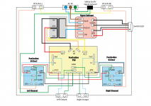
For speaker output and speaker return connection cat5 is fine. For signal input from RCA to the amplifier channels use shielded coaxial wires. During soldering the input cables to the RCAs you can leave the --0V input (gnd) conductor alone and then first short the two RCA's gnd connectors together with a wire. Then solder a wire in the middle of the shorting wire and route the other end of the wire to PSU GND output. I guess Joshua did something like this.
Another question....
In my previous amplifier (LM3886) I used a 1.6A slow blow fuse before the transformer (on 230V mains). Is that rating OK for this setup (+/-25V 300VA toroidal)?
If you're using a similar VA rated transformer and PSU capacitor bank is similar then 1.5A slowblow is fine. If these are larger in this case then use a 3A one.
Also does having a soft start make a difference to whether it should be a fast or slow blow?
Cheers
Neal
Yes. The softstart limits inrush so a fastblow can be used. If there is no softstart then the inrush current may be sufficient to melt the wire of a fastblow, better use a slowblow.
Just a reminder, use only fastblow fuses between the psu and amplifiers, i.e. in the fuse holders on PSU board.
Thanks for replying Shaan...
I think I've got this now then, does my updated diagram accurately represent what you are suggesting? I don't actually need to do anything with the shield of the coaxial cable?
Really looking forward to getting this built. I'm ordering the traffo this week and the case will have to wait for next month's pay packet.
For speaker output and speaker return connection cat5 is fine. For signal input from RCA to the amplifier channels use shielded coaxial wires. During soldering the input cables to the RCAs you can leave the --0V input (gnd) conductor alone and then first short the two RCA's gnd connectors together with a wire. Then solder a wire in the middle of the shorting wire and route the other end of the wire to PSU GND output. I guess Joshua did something like this.
I think I've got this now then, does my updated diagram accurately represent what you are suggesting? I don't actually need to do anything with the shield of the coaxial cable?
Thanks, I'll be using +/-25v 300VA with 4x10,000uF capacitors and the softstart so the correct fuse will be 1.5A with fast blow then.If you're using a similar VA rated transformer and PSU capacitor bank is similar then 1.5A slowblow is fine. If these are larger in this case then use a 3A one.
Yes. The softstart limits inrush so a fastblow can be used. If there is no softstart then the inrush current may be sufficient to melt the wire of a fastblow, better use a slowblow.
Thanks, I have got the fast blow fuses fitted already but it's always good to have it confirmed.Just a reminder, use only fastblow fuses between the psu and amplifiers, i.e. in the fuse holders on PSU board.
Really looking forward to getting this built. I'm ordering the traffo this week and the case will have to wait for next month's pay packet.
Last edited:
- Home
- Group Buys
- PeeCeeBee V4 GB!