Great googly moogly! It's 2020 and people are still fixing CS800s....I'm not surprised one bit!
See if you’re cute little seven pound class D amp is still working in 40 years. And if it can even be fixed if it isn’t.
Of course, if you're feeling adventurous, you could just gut the thing and use the massive transformer, heat sinks and chassis for your own design. The transformer appears to have sufficient capacity for a 4 ohm bridge stable amp for short duty cycle applications like subwoofers.
.
We used to run them bridged into 4 ohms back in the 80’s. 5 pairs of MJ15024 will actually do that on 80v rails with no problems. Compare a comparably rated modern class AB (RMX1450) with only 3 pairs of flatpacks, a LOT LESS heatsink, claiming 2 ohm stability. Runs hotter than the blazes of Hell And Damnation doing it. In 40 years they’ll all be in the landfill.
Well in good news, the amp that was supposedley good, is good. Before I hooked it up to anything, I checked for DC on the outputs, 22mV on channel A and 1 or 2mV on channel B, so it seems fine. I opened it up to have a cursory glance to see how easy it would be to pop out the mains cable grommet and re-secure the mains cable, I realized I'd probably need to pull off the input and output boards to gain access, and just left it for now. Also noticed the drivers (two rightmost) on Channel A have been replaced with NTE devices.
Mica washers ordered, and on their way, my main worry is the screws used to hold the TO-3's in to the socket, they look kinda like tech screws, what do you call them, and where can you get them? I'm guessing I need the right kind so they go into the socket, don't mung it up, and don't short out on the heatsink?
Other than that I'm pretty sure I can find hardware to hold the heatsinks down and put the lid on and stuff.
You are missing the transistor screws? They are just sheet metal screws. Of course they need to be the right size.
Agree and add: as far as I remember they were not your average "corner hardware store" sheet metal screws but a finer pitch version for better grip-
I guess plain vanilla ones have too coarse threads.
Don´t you have at least one original screw left so as to measure it?
Both exact diameter and pitch.
I guess plain vanilla ones have too coarse threads.
Don´t you have at least one original screw left so as to measure it?
Both exact diameter and pitch.
The screws can be US machine screws #4-40 3/8" to 1/2" long with serrated washer nuts. Or 3 mm screws with serrated washer stop nuts. The original transistors would accept #6-32 or 4 mm screws, but the newer ones like mj21193/4 that look like TO-3 have smaller holes that don't fit #6. I buy screw hardware from mcmaster.com in the US because you can get ****** ones instead of *****, but you might have a grainger outlet, mcs direct outlet, or fastenal dealer in Jamaica that is more convenient. Let the store deal with border theft if you can. Newark(farnell) sells the screws but they only have ordinary nuts, not serrated washer ones. Peavey uses the screws to connect the collector to the PCB land, so serrated washer nuts (stainless) give better connectivity. McMaster-Carr You could also buy stainless serrated washers separately.my main worry is the screws used to hold the TO-3's in to the socket, they look kinda like tech screws, what do you call them, and where can you get them? I'm guessing I need the right kind so they go into the socket, don't mung it up, and don't short out on the heatsink?
Peavey's have big holes for the OT emitter & base leads; if you tighten them while looking you can keep from shorting the leads to the heat sink. Check afterwards with ohms scale of DVM of course, B & E don't touch C.
But if you buy the mica washer kits from farnell, multicomp brand, they come with plastic ferrules to keep the transistor leads from touching the heat sink.
Last edited:
Hey Jo, I think maybe yours (or mine) have been modded? I have socketed TO-3's, which is what I've been asking about as I'm not really sure of the procedure with sockets, usually it's like you said a full insulator kit, with washer, and insulators for the pins and bolts.
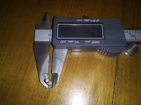
Anyway the first 5mm or so of the shank is smooth, which I'm guessing isn't super critical but probably just helps center it in the socket?
Not really familiar with US/Imperial sizes, but I'm guessing this makes it a #4 x 3/4" or maybe 1/2" given I'm including the head.
Anyway the first 5mm or so of the shank is smooth, which I'm guessing isn't super critical but probably just helps center it in the socket?
Not really familiar with US/Imperial sizes, but I'm guessing this makes it a #4 x 3/4" or maybe 1/2" given I'm including the head.
Attachments
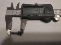
That is a sheet metal screw. Not a machine screw. The unthreaded part is for self align with a auto-feed air gun, just jam it at the hole and the thin part will line it up. Unthreaded part is not necessary for hand assembly.
Conversion mm to in is 25.4 mm/inch. 1 mm is .0394 inch. #6 machine screw fits through a .140" clearance hole, #4 fits through a .089" clearance hole. Numbered sheet metal screws are about the same size as machine screws of that number but are not precise.
Round head screws the nominal length does not include the head, only the shaft. Flat head screws the nominal length includes the head. To measure the clearance hole your screw goes through, use the flat part of the caliper arms to measure over the outside of the threads at the fat part.
If you're CS800 has socketed output transistors it is a dinosaur. Manufacturers got away from those because the brad that clenches the emitter & base peg loses connection due to oxide over the decades. All the peaveys amps I've worked on have emitter & base legs soldered to a trace on the board.
You'll notice on the On semi datasheets, the new transistors like MJ21194 have a clearance hole that is .131" minimum or 3.3 mm minimum. The old MJ15024 transistors used to have a hole that would clear .140" #6 screw, but the new MJ15024 datasheet references the smaller hole. Case is now called TO204AA, not TO3.
Last edited:
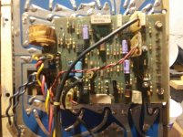
OK, I think I have the Series A (with Series C driver boards) semi-sorted. I spent some time straightening out the header pins on the Channel A output module and got the driver board fitted.
Channel B (picture with my fingers in it) was all hooked up already, so I used it as a model for Channel A and oriented the heatsink the same way round, as the cables had enough flex to let me do so.
Channel B had one extra 3-pin connector used, and there was only a single pin cable left on Channel A, so at first I thought just connect the single pin to the middle of the 3-pin. However after looking at the handy schematic / layout for Rev C that Enzo provided (thanks again) I saw that the 3 pin connector was connecting to R12 (thank god for the layout), which leads to the inverting input on the op-amp, and that there should be a single post from R34 which is the signal for bridge out.
To confirm, I ohmed out the loose single pin connector to the 3-pin on the Channel B board, and when the Stereo / Bridge switch is put in Bridge, they are connected, so I'm pretty confident that it's the bridge out connector, and that there is not 3-pin for Channel A, as it doesn't need an inverted output in Bridge mode.
So I should get my mica TO-3 (or maybe TO-224AA, it said it was TO-3) insulators tomorrow, I think I found some suitable metal screws from an old UK 13A plug, I can only fit it all up, and check for shorts. Then I can power it on see what I need to do for it. Then on to finding some hardware to hold it all together (heatsinks, cover, etc.).
Yay. Thanks for all the help so far guys.
Attachments

Last edited:
Hmm, every single can on the output module of channel 1 is near low ohms to the heatsink, on channel 2, only half of them, which I'd expect as the collectors are grounded on half the unit.
So either a shorting device, or a triac fault maybe?
So either a shorting device, or a triac fault maybe?
On the side with the output transistor emitters connected through .33 ohms to speaker hot, the collectors can be all shorted together, as they are all +80 v. If shorted to the heat sink, the heat sink has to be on insulators to the case, which is speaker return.
On the side with the OT collectors going to speaker hot, the OT collectors can be shorted together but if shorted to heat sink, again the heat sink has to be insulated from case. Look for plastic ring washers around the heat sink mount. These could discintegrate in 40 years.
Never took an A apart to see how the heat sink was mounted.
Note I said output transistors collectors are connected through screws to the circuit board. Definitely on later models. Not sure of your OT socket comment, the picture didn't show that. But if there is a circuit board for output transistors, the screw to output transistor case has to touch PCB land for collector current to flow. Click on the mcmaster link post #105 to see picture of a star washer 4-40 nut that will make sure that connection to pcb land is made. If actual phenolic sockets, the connection to collector has to be made with a wire soldered to the post on the socket. I've got a schober recital organ 15W amp with phenolic socketed TO3 output transistors, but no peavey products.
There is an apparent drawing error on schematic. 1/4 jack is shown as tip touching ring unplugged. Ring is case ground or speaker return, that cannot be.
If the DC protection triac was shorted, the speaker hot would be shorted to speaker return and case ground all the time.
Last edited:
First thing I'd check would be if someone assembled it with no insulating wafers on that module.
Triac is easy to test, just measure resistance between black and red speaker posts on the rear. The triac is wired between them. If they measure shorted together, your triac is almost surely blown.
Triac is easy to test, just measure resistance between black and red speaker posts on the rear. The triac is wired between them. If they measure shorted together, your triac is almost surely blown.
1.8 ohms between red and black.
I figure that the 4 pin connector that's on the output board rather than the drive is the output connector (and probably the power too) and the layout seems to confirm this.
If I unhook that output module connector, I still have about 2 ohms between red and black speaker terminals AND none of the cans ohm out to ground anymore (on either module channel A or B), so it looks like the crowbar did it's job, I suppose I'll have a blown fuse as well.
For testing the amp will work fine without the triac, so remove the shorted triac and you can test the rest of the circuit.
Oh wow, so the board is just bolted to the back of the speaker terminals, and just pops off, no other connections. That's a nice design.
I was a little confused by the middle pin of the thyristor (SAC187) being clipped, until I realised it's connected via the body of the device instead.
I was a little confused by the middle pin of the thyristor (SAC187) being clipped, until I realised it's connected via the body of the device instead.
Has anyone any experience of these little circuit breakers that seem to be to replace fuseholders?
Amazon.com: Potter Brumfield Circuit Breaker 15 Amp 120v Push Thru W28XQ1A-15: Sports & Outdoors

I'm wondering if they'd have a problem with the inrush current on such a large transformer?
After going thru pretty much every piece of junked equipment, and some not junked equipment, I don't have a replacement fuseholder insert that fits the current fuseholder on the CS-800 and if I'm going to have to replace the whole holder, I might as well update it. I had planned to just put in a 10A fuse (biggest I have on hand) and see if it would power up.
Amazon.com: Potter Brumfield Circuit Breaker 15 Amp 120v Push Thru W28XQ1A-15: Sports & Outdoors
I'm wondering if they'd have a problem with the inrush current on such a large transformer?
After going thru pretty much every piece of junked equipment, and some not junked equipment, I don't have a replacement fuseholder insert that fits the current fuseholder on the CS-800 and if I'm going to have to replace the whole holder, I might as well update it. I had planned to just put in a 10A fuse (biggest I have on hand) and see if it would power up.
They work, I used to stock them in various ratings.
Please don't just power it up to see what happens. Either bring it up on a variac while monitoring the mains current, OR build a "light bulb limiter" and USE it.
Please don't just power it up to see what happens. Either bring it up on a variac while monitoring the mains current, OR build a "light bulb limiter" and USE it.
To deal with in-rush current, you could always build one of these to deal with that:
Soft-Start Circuit For Power Amps
Soft-Start Circuit For Power Amps
Wouldn't I need a pretty huge variac? Something as big as the xfmr? I have a variac, but I don't think it's that big. I'll have to see if I can find the VA rating for it, got it surplus 20-odd years ago.
Irony, I'll have to find an incandescent bulb to use as a limiter 😀
Irony, I'll have to find an incandescent bulb to use as a limiter 😀
The use of a vriac is to determine if the unit is going to draw excess current. The variac does not have to provide full power for the amp at max output. I am bringing up the amp at idle, not at power. So my 3000 watt amp, for example, should only draw 50-100 watts at idle. If I start up the variac and see it draws 4 amps already at only 20v, I STOP and turn back down because that indicates trouble.
For bulb limiters, we may have a hard time finding a plain 100 watt or 60 watt bulb, but they still exist as specialty lamps. For example flood lights or heat lamps, also tough duty lamps for work lights.
For bulb limiters, we may have a hard time finding a plain 100 watt or 60 watt bulb, but they still exist as specialty lamps. For example flood lights or heat lamps, also tough duty lamps for work lights.
Yes, the incandescent lamps are a bit uncommon. I built a dim bulb limiter and was able to find 100, 60, and 25 watt bulbs to use depending on the equipment under test. For sure, I'd rather have a variac, but for those of us on a VERY limited budget these days, a dim bulb tester is an EXCELLENT addition to my work bench.
- Home
- Live Sound
- Instruments and Amps
- Peavey CS-800 Issues