simple question, new diyer need help i have finished my boards and psu if iwant to set p1 to zero volt how and where i put the positive and negative lead of my mutimeter and please dont answer me with my hands iam new and i want to make sure i have the correct way to do it thank everybody in advance pierre
Connect black meter probe to ground and red one to 10 Ohm output resistor.
Set P1 for Zero. You may measure either side of resistor. You will see a little drift.
Set P1 for Zero. You may measure either side of resistor. You will see a little drift.
Open loop gain is about 75 - 80 dB.
Q2 does increase the gain. It is a level translator but functions as a common source amplifier. It is just a P channel with no source resistance feeding a current source.
The current source looks like a large value resistance.
Q2 does increase the gain. It is a level translator but functions as a common source amplifier. It is just a P channel with no source resistance feeding a current source.
The current source looks like a large value resistance.
thank you wayne for your help,i really appreciate and congratulation for a fantastic work thank you so much pierre 
Open loop gain is about 75 - 80 dB.
Q2 does increase the gain. It is a level translator but functions as a common source amplifier. It is just a P channel with no source resistance feeding a current source.
The current source looks like a large value resistance.
Hi, thanks for the explanation.
Also, if we cascode the current source to make the 2nd stage bias current more stable... that will help?
Would it be possible to build a Pearl 2 using 4 12 volt SLA batteries to generate the 24 volt rails? Would you still need any of the regulator circuitry if you did?
Gents, thoughts on the sonic characteristics of C13 ? Wayne specified an Elna Silmic II, but I found some Black Gates on Micheal Percy's site of the same value. Any opinions on which to use. Also would a non-polarized electrolytic work better here?
I am using Marsh Multicaps everywhere else.
Also how does this circuit compare to Pass XP-15 / XP-25 ? Anthony Cordesman really liked the XP-25 in the January 2011 TAS.
I am using Marsh Multicaps everywhere else.
Also how does this circuit compare to Pass XP-15 / XP-25 ? Anthony Cordesman really liked the XP-25 in the January 2011 TAS.
Gents, thoughts on the sonic characteristics of C13 ? Wayne specified an Elna Silmic II, but I found some Black Gates on Micheal Percy's site of the same value. Any opinions on which to use. Also would a non-polarized electrolytic work better here?
I am using Marsh Multicaps everywhere else.
Also how does this circuit compare to Pass XP-15 / XP-25 ? Anthony Cordesman really liked the XP-25 in the January 2011 TAS.
I personally used the new Muse green series, as it seem to have very good value for the money. It's a non polarized model. I guess each model (Silmic, BlackGate ...) will make the sound a bit different. There is no rule of thumb here. Modding the layout you could even use a polypropylene foil cap.
I can't compare to XP-15 / XP-25 as I don't have them 🙂 The basic circuit itself (Pearl II) is very nicely done. To make small sonic quality gains, one could use a shunt reg PSU instead of the 78XX/79XX on board. If the shunt is nicely done it can give a better sound. I think about Salas' shunt reg, for example 🙂
Best,
nAr
22 mfd film capacitors
These are REAL BIG and Expensive......but maybe worthwhile. I would guess mounting between the PC boards and the output RCA jacks would work best. Anybody tried this ?
These are REAL BIG and Expensive......but maybe worthwhile. I would guess mounting between the PC boards and the output RCA jacks would work best. Anybody tried this ?
These are REAL BIG and Expensive......but maybe worthwhile. I would guess mounting between the PC boards and the output RCA jacks would work best. Anybody tried this ?
It can be done, in order to do so you can also mount the 100k after the capacitor out of the board too, directly soldered to the RCA leads. The grounding scheme can suffer however, as if you decide rewire (for hum problems) it can lead you to difficult ways. You also need to solder the 100 nF bypass capacitor out of the board too, and place extra jumpers accordingly 😎
nAr
Nar, my thoughts, also, however, if you use a good film cap for C13, you probably don't need a bypass cap. The Marsh Multicaps are constructed such that they are actually 10 smaller caps run in parallel to give a lower ESR at high frequencies in a single ( fat) package.
That said, I think I'm going to try a Silmic in one channel and a Black Gate in the other, and see which one I can live with.
That said, I think I'm going to try a Silmic in one channel and a Black Gate in the other, and see which one I can live with.
Nope, you'll need that one :
The σ22 Regulated Power Supply
But please bear in mind that if you build the original Pearl II, the regulators (7824 & 7924) are already on board with a passive Pi filter. You only need to build a symmetric PSU with just diodes bridges and first filtering reservoirs. That's what I did, as per Wayne's pdf. The RIAA is dead silent 🙂
Regards,
nAr
Nar, my thoughts, also, however, if you use a good film cap for C13, you probably don't need a bypass cap. The Marsh Multicaps are constructed such that they are actually 10 smaller caps run in parallel to give a lower ESR at high frequencies in a single ( fat) package.
That said, I think I'm going to try a Silmic in one channel and a Black Gate in the other, and see which one I can live with.
Please tell us your listening comments about sonic signature for those capacitors 🙂 Thanks 🙂
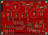
I did my own PCB, smaller than the standard PassLabs design. It fits on 6''x9'' double side PCB material sheet I used. I got very nice Mundorf M-Lytic power supply caps, Vishay RN-60D resistors all around, and 0.1% CMF-55 resistors at key locations. These are the top and bottom layers, one channel. Both channel fits on 6''x9''
Attachments

I did my own PCB, smaller than the standard PassLabs design. It fits on 6''x9'' double side PCB material sheet I used. I got very nice Mundorf M-Lytic power supply caps, Vishay RN-60D resistors all around, and 0.1% CMF-55 resistors at key locations. These are the top and bottom layers, one channel. Both channel fits on 6''x9''
Very nice design 😉
Slyvain, check your PL on the size and output of your tranny... An Rcore would beat the philtron at these levels
Regards
David
Regards
David
I did my own PCB, smaller than the standard PassLabs design. It fits on 6''x9'' double side PCB material sheet I used. I got very nice Mundorf M-Lytic power supply caps, Vishay RN-60D resistors all around, and 0.1% CMF-55 resistors at key locations. These are the top and bottom layers, one channel. Both channel fits on 6''x9''
... and you kept the "square landing areas" I added ! 🙂
I must say, they are nice to live with.
Soldering on top of the board only is easier, also thanks to the "vias" 😎
I perfectly agree for a RCORE transformer, it makes sense for all line levels applications, DACS, preamps, active filters ...
Best,
nAr
- Home
- Amplifiers
- Pass Labs
- Pearl Two