Wayne,
Would it be possible to see some shots of your finished Pearl 2? I would love to see how you laid it out, wired it and so forth. I'm still putzing around with ideas, but am having difficulty proceeding, as I really want this one right the first time! It's fine if this isn't possible, just asking!
Thanks,
Russellc
Wayne,
Would it be possible to see some shots of your finished Pearl 2? I would love to see how you laid it out, wired it and so forth. I'm still putzing around with ideas, but am having difficulty proceeding, as I really want this one right the first time! It's fine if this isn't possible, just asking!
Thanks,
Russellc
Yes, Wayne, I second that 😉
Not to be a Whiner, I just want this component to be quiet as possible and not have to re assemble it to get it quiet. Again, if not possible its no big deal. Would be nice to see how it should be done
Pretty please, (if possible)
russellc
Pretty please, (if possible)
russellc
Not to be a Whiner, I just want this component to be quiet as possible and not have to re assemble it to get it quiet. Again, if not possible its no big deal. Would be nice to see how it should be done
Pretty please, (if possible)
russellc
Will show you what I did as soon as the project is completed
I intend to run with single PSU
Try with V+ GND V- at each board
Input gnds separate
Use Wayne's wiring scheme for PSU
It should be OK
Best regards,
nAr
I think I have some photos stashed. I will see what I can find.
Much appreciated!
Russellc

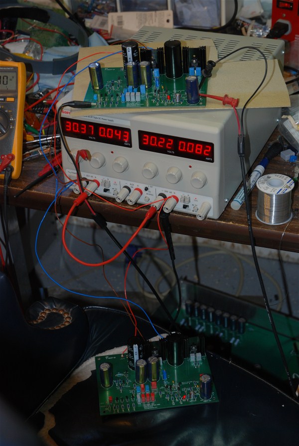
Here is a photo from my home bench. I am putting these in a box soon.
Quite glamorous! 😀
---
nAr, the boards seem to have come out quite nicely!
I have not yet begun to work on this as I've been busy with non-audio things of late. But as the air grows colder I may move back inside soon 🙄
Quite glamorous! 😀
Yes, it's the epic. The bench is nice and Wayne has oscilloscope too, seen the probes.
nAr, the boards seem to have come out quite nicely!
I have not yet begun to work on this as I've been busy with non-audio things of late. But as the air grows colder I may move back inside soon 🙄
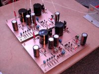
You're welcome 😛 Yes, boards have come out quite easily. As of today I've finished populating the boards. Some random comments:
- I started drilling the boards with a cheap hand micro-driller and it turned out that it's impossible to be 100% vertical this way. I mean, for a single sided board it can be OK, if you're drilling for copper side and accept some incoherency. For the double sided board, it can come out catastrophic. I ended up using the big drill press from the basement, yes even 0,8 mm drills fit well inside the drill cylinder, once screwed there is no bad move and I could adapt the drilling speed to about 1500 RPM, so the drills keep a better shape thorough the job. Remember, about 360 holes for a stereo set.
- I ended up using some 5% MKT for the 0,1 uF parts, mostly because the MKP 1% versions from Vishay weren't available . However, I matched them by hand from a batch of 50 to get a better accuracy, and they are always bypassed by the MKP 1% values anyway (0,01 and 0,033 uF). Even the MKP were matched with the capacimeter to get real precise values down to 0,1%. I just hope it will be worth the effort 🙂
- I used 2 match quads @6,30-6,27-6,29-6,30 mA and 6,13-6,19-6,16-6,19 mA and the Dale 10 ohm resistors, and 2 matched pair @ 5,81-5,80 and 5,89-5,88 mA for the differential. No problems for implementing, but I juste hope it works 🙂
- For now PSU is ready, I used a 300VA 2x24V RCore, it's ridiculous but it was lying around ... then suggested Wayne's PSU as seen in the article. I found a small mica 500V 0,0033 uF for mains pre-filtering. For now the PSU works, tested last night.
So what ? Now is the testing part ... I have to do this today. I hope it'll go fine, hey wish me good luck. If I'm fast enough, I will post some pictures later today. I need to secure the boards on a testing plane before plugging ... and also have the in and outs (provisoire) ready for listening.
Best,
nAr
EDIT: One board is up and, worked on the first time 🙂 !
I did some basic values measures for now. The components have not reached the operating temperature yet
R21 46,9 mV
R22 46,9 mV
R23 47,3 mV
R24 47,3 mV
Assuming the 10R 1% resistors, and resistor & jfet slight mismatch, this gives about 4,69 and 4,73 mA per se,
for a total of 18,84 mA for the first stage
R28 1,157V so slightly more than 2 mA
R29 1,164V so about 11,64 mA on the ZVP 3310 output stage
(I used same red led as Wayne did)
Offset was easily trimmed to 0V by P1.
It seems to wander a little, from -5 mV to +2mV perhaps but I guess it's quite fine.
Perhaps better offset stability could be achieved by thermally coupling Q4 and Q5 ?
Active power consumption for one board is 32,78 mA. To this I must add the voltage drop on the regulators,
because I have + 36V / - 35,9V at the input of the board.
Clearly, a 22V transformer would be a better choice, it would help lower the dissipation on the regulators.
The sinks run quite cool though. The red led effect is cool too ;p
The inputs are not grounded. Should have done. Once I have set the 2 boards,
I will mount I/O and re-run some tests, then listening.
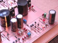
I try to up some pics. Note that some components are elevated from the board to achieve the ability of soldering on the components side 🙂
Cheers,
nAr
I did some basic values measures for now. The components have not reached the operating temperature yet
R21 46,9 mV
R22 46,9 mV
R23 47,3 mV
R24 47,3 mV
Assuming the 10R 1% resistors, and resistor & jfet slight mismatch, this gives about 4,69 and 4,73 mA per se,
for a total of 18,84 mA for the first stage
R28 1,157V so slightly more than 2 mA
R29 1,164V so about 11,64 mA on the ZVP 3310 output stage
(I used same red led as Wayne did)
Offset was easily trimmed to 0V by P1.
It seems to wander a little, from -5 mV to +2mV perhaps but I guess it's quite fine.
Perhaps better offset stability could be achieved by thermally coupling Q4 and Q5 ?
Active power consumption for one board is 32,78 mA. To this I must add the voltage drop on the regulators,
because I have + 36V / - 35,9V at the input of the board.
Clearly, a 22V transformer would be a better choice, it would help lower the dissipation on the regulators.
The sinks run quite cool though. The red led effect is cool too ;p
The inputs are not grounded. Should have done. Once I have set the 2 boards,
I will mount I/O and re-run some tests, then listening.
I try to up some pics. Note that some components are elevated from the board to achieve the ability of soldering on the components side 🙂
An externally hosted image should be here but it was not working when we last tested it.
Cheers,
nAr
Last edited:
Very nice job! Your boards turned out excellent and look quite professional!
Cheers,
Russellc
All credit to eclectic2k for helping me with layout & routing 😛
Hi Nar,
Very nice job indeed 🙂 and congratulations for getting it working at the first run. The Mundorf caps look quite nice 😉
Looking forward to hearing it soon...
Cheers,
Dominique 😀 alias "facelvega"
Very nice job indeed 🙂 and congratulations for getting it working at the first run. The Mundorf caps look quite nice 😉
Looking forward to hearing it soon...
Cheers,
Dominique 😀 alias "facelvega"
Here is a photo from my home bench.
I am putting these in a box soon.
Nice bench ... Entropy rules 🙂 ... The way I like it ...
Manu
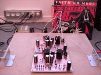
Done and up !
My Pearl II prototype is finished 🙂
I really enjoy it. Sound is very firm and relaxed, no harshness, naturally detailed. Bottom is firm and layering is excellent. I'm doing some more burn-in tests.
Here are some views of the finished prototype. Next post I'll describe the grounding path scheme I used, it's very simple and there is no buzz or rumble at all 🙂
Cheers from France,
nAr
Attachments
YIt seems has negative feedback in 2nd stage (and could control the gain here)?

- Home
- Amplifiers
- Pass Labs
- Pearl Two