400uFFolkdeath:
You mentioned the cap in series with R14 as Wayne recommended.
What was the value of the cap and what was the rationale to add it ?
Can you point me to the post(s) where this was discussed ?
Sorry for asking questions that are covered elsewhere but I looked back through the thread and could not find it.
http://www.diyaudio.com/forums/pass-labs/204336-building-pearl-2-a-77.html#post4947298
The cap keeps the DC gain at unity making the DC offset more stable. 47 uF - 470 uF works fine as a value 16 Volt or more use a film bypass if you want.
I remember someone earlier mentioned that after adding this cap they removed P1 and changed the value of a resistor. Is that necessary? Also, does this effect use of the output cap and have any effect on sound? Sorry for all the questions. I can follow a schematic but have no idea when it comes to designing circuits. I'm just trying to understand the reasoning behind some of the changes made to the circuit and the overall effect of those changes.
Thanks & Best Wishes,
Bob
Thanks & Best Wishes,
Bob
Leave P1 in it adjusts the DC offset. You can maybe remove the output coupling cap if you use the cap in series with R25. Short the cap out with a clip lead adjust P1 for the best you can get then remove the clip lead.
Coincidentally ??, I have an SP-10 that is in line for restoration.
I purchased it after seeing the Pass table (Wayne's ??) online somewhere and then reading your experience with yours in the Incredible SP-10 thread.
I didn't know about a Pass SP10 or about 6L6's thread. I have to read that.😉
Good luck with the power supply in the same box, I belive you will be the first to make that work.6c4c:
Yes, I plan to add shielding between PSU and Pearl boards.
I will try some different approaches and post the results here.
I would keep an alternative remote power supply plan just in case.
Russellc
Russellc:
Yes, I recognize that I may very well end up with a two box solution.
I will start with a single box solution then progressively add shielding.
A buddy of mine has an analyzer so we can measure the results and post them here.
Hopefully they will stimulate some good discussion that might benefit others.
First I need to finish building it which looks like might get done this weekend 🙂
Berd
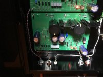
It's alive... I finished building my Pearl II tonight
I brought it up slowly with the variac and all the voltages looked pretty good.
It was hard adjusting P1 to zero but I got it down to +/- 4 to 7 mV.
Anything below that and the pot is just too twitchy.
The smallest adjustment I can make moves the voltage 5 mV or more.
All the supply voltages look good but there are a couple of other voltages that are slightly off.
When tuned for ~ 0V the voltage across R6 is 1.548 on the right channel and 1.658 on the left channel.
The voltage at the R8, R10, Q3 node was L = 7.427 and R = 7.488
At the R9, Q3 node was L=6.788 and R = 6.852
Thoughts, comments, and suggestions welcome.
After checking voltages and seeing no oscillations on the outputs (with inputs shorted) I hooked it up in the system and listened to some music.
I think I have more than enough (perhaps too much ?) gain for the Ortofon 2M Black.
It is way louder (about 6 dB) when I switch inputs back a forth between the same song on the Oppo versus the Pearl II
I don't think I hear any obvious distortion but have only listened to a few albums.
I'll give some more observations once I have let it run for a while and get some better impressions but so far it is sounds pretty darned good.
How about the hum ?
I find myself listening at a level of 45 to 50 on the preamp.
A level of 60 is really loud and I would not listen long at that level.
With the needle raised I don't begin to hear any hum until I get the volume level above 65.
It is certainly not objectionable/audible with the needle raised at what would be any sane volume levels.
That said I will still likely add some shielding just for grins and report the results.
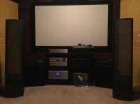
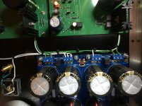
One lousy interior picture from the phone for now but I'll get my camera out in the morning and a couple better ones when I have more light.
From the outside it looks pretty good in the rack (top left) and matches the rest of the Pass gear pretty well - which was one of my goals.
Thanks for all the support from 6L6 and all the folks here.
Also, MANY thanks to Wayne for giving us great projects to work on and being patient with all our questions.
I brought it up slowly with the variac and all the voltages looked pretty good.
It was hard adjusting P1 to zero but I got it down to +/- 4 to 7 mV.
Anything below that and the pot is just too twitchy.
The smallest adjustment I can make moves the voltage 5 mV or more.
All the supply voltages look good but there are a couple of other voltages that are slightly off.
When tuned for ~ 0V the voltage across R6 is 1.548 on the right channel and 1.658 on the left channel.
The voltage at the R8, R10, Q3 node was L = 7.427 and R = 7.488
At the R9, Q3 node was L=6.788 and R = 6.852
Thoughts, comments, and suggestions welcome.
After checking voltages and seeing no oscillations on the outputs (with inputs shorted) I hooked it up in the system and listened to some music.
I think I have more than enough (perhaps too much ?) gain for the Ortofon 2M Black.
It is way louder (about 6 dB) when I switch inputs back a forth between the same song on the Oppo versus the Pearl II
I don't think I hear any obvious distortion but have only listened to a few albums.
I'll give some more observations once I have let it run for a while and get some better impressions but so far it is sounds pretty darned good.
How about the hum ?
I find myself listening at a level of 45 to 50 on the preamp.
A level of 60 is really loud and I would not listen long at that level.
With the needle raised I don't begin to hear any hum until I get the volume level above 65.
It is certainly not objectionable/audible with the needle raised at what would be any sane volume levels.
That said I will still likely add some shielding just for grins and report the results.
One lousy interior picture from the phone for now but I'll get my camera out in the morning and a couple better ones when I have more light.
From the outside it looks pretty good in the rack (top left) and matches the rest of the Pass gear pretty well - which was one of my goals.
Thanks for all the support from 6L6 and all the folks here.
Also, MANY thanks to Wayne for giving us great projects to work on and being patient with all our questions.
Attachments
Last edited:
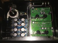
I ordered the parts from Mouser that I needed for the power supply last Monday and received them on Thursday. I picked up a case from Par Metal (now Pi-Metal) over the weekend and finished the supply this morning. Voltages are +30.48 and -30.49 so all looks good. Used my light bulb tester for 1st startup since I don't have a variac. Had it on for a couple of hours and all remains stable. Here's a couple of photos:
 [/URL][/IMG]
 [/URL][/IMG]
 [/URL][/IMG]
Very nice Berd!
BTW, did you build the Pearl 2 as is or did you have to increase the source resistors of
the jfets in the first stage?
http://www.diyaudio.com/forums/pass-labs/156397-pearl-two-265.html#post4687356
Cheers,
Dennis
BTW, did you build the Pearl 2 as is or did you have to increase the source resistors of
the jfets in the first stage?
http://www.diyaudio.com/forums/pass-labs/156397-pearl-two-265.html#post4687356
Cheers,
Dennis
Dennis:
I debated building as is with 10R or with 20R resistors in the first stage.
Jim (6L6) recommended building as is and getting it up and running before tweeking it.
I don't hear any obvious / gross distortion but I just listened to about 6 record sides last night and one this morning before work.
It is much louder than the other sources so I think I want to reduce the overall gain and changing to 20R resistors in the first stage should help that.
Now the fun begins - one change at a time 🙂
Dennis:
I debated building as is with 10R or with 20R resistors in the first stage.
Jim (6L6) recommended building as is and getting it up and running before tweeking it.
I don't hear any obvious / gross distortion but I just listened to about 6 record sides last night and one this morning before work.
It is much louder than the other sources so I think I want to reduce the overall gain and changing to 20R resistors in the first stage should help that.
Now the fun begins - one change at a time 🙂
Gain in the first stage is your friend -- if you need to shave gain, do it later. Why parallel 4 JFET's if you're gonna worsen noise?
Pass DIY Addict
Joined 2000
Paid Member
If you are using a high gain (5mV) MM cartridge like I did, you'll need to use 20R resistors on Q6 through Q9 to prevent distortion in the first gain stage.
I brought it up slowly with the variac and all the voltages looked pretty good.
It was hard adjusting P1 to zero but I got it down to +/- 4 to 7 mV.
Anything below that and the pot is just too twitchy.
The smallest adjustment I can make moves the voltage 5 mV or more.
All the supply voltages look good but there are a couple of other voltages that are slightly off.
When tuned for ~ 0V the voltage across R6 is 1.548 on the right channel and 1.658 on the left channel.
The voltage at the R8, R10, Q3 node was L = 7.427 and R = 7.488
At the R9, Q3 node was L=6.788 and R = 6.852
Thoughts, comments, and suggestions welcome.
After checking voltages and seeing no oscillations on the outputs (with inputs shorted) I hooked it up in the system and listened to some music.
I think I have more than enough (perhaps too much ?) gain for the Ortofon 2M Black.
It is way louder (about 6 dB) when I switch inputs back a forth between the same song on the Oppo versus the Pearl II
I don't think I hear any obvious distortion but have only listened to a few albums.
I'll give some more observations once I have let it run for a while and get some better impressions but so far it is sounds pretty darned good.
How about the hum ?
I find myself listening at a level of 45 to 50 on the preamp.
A level of 60 is really loud and I would not listen long at that level.
With the needle raised I don't begin to hear any hum until I get the volume level above 65.
It is certainly not objectionable/audible with the needle raised at what would be any sane volume levels.
That said I will still likely add some shielding just for grins and report the results.
One lousy interior picture from the phone for now but I'll get my camera out in the morning and a couple better ones when I have more light.
From the outside it looks pretty good in the rack (top left) and matches the rest of the Pass gear pretty well - which was one of my goals.
Thanks for all the support from 6L6 and all the folks here.
Also, MANY thanks to Wayne for giving us great projects to work on and being patient with all our questions.
Nice, if you are getting no hum, amazing! You are going to love this thing!
Russellc
Dennis:
I debated building as is with 10R or with 20R resistors in the first stage.
Jim (6L6) recommended building as is and getting it up and running before tweeking it.
I don't hear any obvious / gross distortion but I just listened to about 6 record sides last night and one this morning before work.
It is much louder than the other sources so I think I want to reduce the overall gain and changing to 20R resistors in the first stage should help that.
Now the fun begins - one change at a time 🙂
This is a perfectly good excuse to go low output moving coil shopping! The fun never ends...😀
Russell
Reducing Hum
RussellC:
There are a couple of techniques and perhaps a couple "tricks" I used to reduce hum.
The techniques are:
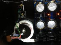
- Use an IEC style AC input jack with integral noise filter. Inside the Pearl enclosure it has a grounded metal housing not plastic. Looking at pictures online this is what Pass does on all their preamps.
- Use a shielded toridal transformer (I used an Antek 5022) and keep it far away from the Pearl inputs
- Keep all AC wiring absolutely as short as possible.
- Route all AC wiring as far away as possible from the Pearl inputs. I also tried to keep DC wiring away from inputs too (always route it away from the inputs on the way to the caps)
- Keep Pearl input wires as short as possible.
- Route all wiring (AC, DC and signal) as close as possible to chassis panels. I even taped the wires down in a couple places.
- Keep wires very close together along their entire length (I used a bunch of small zip ties)
- Where wires need to cross, do it at 90 degree angles and avoid it wherever possible.
- Wire the tonearm ground terminal to the "common" on the Universal PSU board (the common between the positive and negative cap banks (white wires).
-- I followed 6L6 suggestion to use jumpers in all the terminals between the common terminals on pos and neg UPSU boards
- The UPSU boards might also help because all cap wiring is on PCB and very close to chassis case (as opposed to point-to-point wired with the caps pointing up)
- Use a single star ground point for chassis, AC mains ground (Protective Earth), and the "ground-to-common" diode bridge.
One "trick" was to use "quad wire" from the input and output jacks to the Pearl PCB.
A buddy turned me on to it and he used it inside large power inverters, e.g. 500 kW stuff, which is a very electrically noisy environment.
(Imagine a 500 kW Class D amplifier switching 1200V IGBTs at a few kHz.)
The quad wire is designed specifically for noise immunity and the construction helps cancel both electric and magnetic fields.
It has four conductors which are tightly woven together with one pair woven left and right (blue/green) and the other pair woven through the first pair at a 90 degree angle (Orange/Brown).
This stuff I used was factory made but it would be easy to DIY with a little patience.
A more difficult trick is that I have a dedicated 50 Amp circuit with a separate isolated ground that runs directly from my main service panel to a sub-panel right behind the equipment rack.
The sub-panel also has an isolated ground bus in addition to the normal ground wire used to ground the sub-panel enclosure.
I use dedicated circuit breakers and very short runs, i.e. < 1 meter, to each of four duplex outlets.
I used the Hubble isolated ground outlets (the orange ones) and the ground terminal on each outlet is wired back to the isolated ground bus in the sub-panel and from there back to the main service panel on a separate dedicated ground conductor.
While it may seem like a lot of work, it was cheaper than most audio projects and only took a couple of weekends to install.
I'm not sure this last part contributes the the lack of hum in the Pearl but it sure couldn't hurt 😀
RussellC:
There are a couple of techniques and perhaps a couple "tricks" I used to reduce hum.
The techniques are:
- Use an IEC style AC input jack with integral noise filter. Inside the Pearl enclosure it has a grounded metal housing not plastic. Looking at pictures online this is what Pass does on all their preamps.
- Use a shielded toridal transformer (I used an Antek 5022) and keep it far away from the Pearl inputs
- Keep all AC wiring absolutely as short as possible.
- Route all AC wiring as far away as possible from the Pearl inputs. I also tried to keep DC wiring away from inputs too (always route it away from the inputs on the way to the caps)
- Keep Pearl input wires as short as possible.
- Route all wiring (AC, DC and signal) as close as possible to chassis panels. I even taped the wires down in a couple places.
- Keep wires very close together along their entire length (I used a bunch of small zip ties)
- Where wires need to cross, do it at 90 degree angles and avoid it wherever possible.
- Wire the tonearm ground terminal to the "common" on the Universal PSU board (the common between the positive and negative cap banks (white wires).
-- I followed 6L6 suggestion to use jumpers in all the terminals between the common terminals on pos and neg UPSU boards
- The UPSU boards might also help because all cap wiring is on PCB and very close to chassis case (as opposed to point-to-point wired with the caps pointing up)
- Use a single star ground point for chassis, AC mains ground (Protective Earth), and the "ground-to-common" diode bridge.
One "trick" was to use "quad wire" from the input and output jacks to the Pearl PCB.
A buddy turned me on to it and he used it inside large power inverters, e.g. 500 kW stuff, which is a very electrically noisy environment.
(Imagine a 500 kW Class D amplifier switching 1200V IGBTs at a few kHz.)
The quad wire is designed specifically for noise immunity and the construction helps cancel both electric and magnetic fields.
It has four conductors which are tightly woven together with one pair woven left and right (blue/green) and the other pair woven through the first pair at a 90 degree angle (Orange/Brown).
This stuff I used was factory made but it would be easy to DIY with a little patience.
A more difficult trick is that I have a dedicated 50 Amp circuit with a separate isolated ground that runs directly from my main service panel to a sub-panel right behind the equipment rack.
The sub-panel also has an isolated ground bus in addition to the normal ground wire used to ground the sub-panel enclosure.
I use dedicated circuit breakers and very short runs, i.e. < 1 meter, to each of four duplex outlets.
I used the Hubble isolated ground outlets (the orange ones) and the ground terminal on each outlet is wired back to the isolated ground bus in the sub-panel and from there back to the main service panel on a separate dedicated ground conductor.
While it may seem like a lot of work, it was cheaper than most audio projects and only took a couple of weekends to install.
I'm not sure this last part contributes the the lack of hum in the Pearl but it sure couldn't hurt 😀
Attachments
Russellc:This is a perfectly good excuse to go low output moving coil shopping! The fun never ends...😀
Russell
Funny your should mention it...
I was down in the Silicon Valley for work and stopped by "The Analog Room", AKA my favorite record store.
Listened to an Ortofon Cadenza Bronze that sounded pretty sweet.
I've got a couple other projects to finish but it started me thinking.
Pass DIY Addict
Joined 2000
Paid Member
Berd: Congrats on your build! My equipment rack is getting a big tight lately and I've been contemplating rebuilding my Pearl with an inboard power supply. I was originally thinking of using an encapsulated Bel Transformer along with an internal regulator board. It's interesting to hear that the Antek works without throwing noise into the chassis. I'm impressed by your results (and your transformer is even less expensive)!
I see you used some nice resistors in the signal path. I did this as well. Next, I want to experiment with putting a cap in series with R14 and see if I can get rid of the output cap. I also want to play with replacing C12||C16 with a Teflon cap.
Nice work!
I see you used some nice resistors in the signal path. I did this as well. Next, I want to experiment with putting a cap in series with R14 and see if I can get rid of the output cap. I also want to play with replacing C12||C16 with a Teflon cap.
Nice work!
Last edited:
- Home
- Amplifiers
- Pass Labs
- Pearl Two