U102
I used the same poly's I used in the RIAA.
Vishay 416 series, 0.1 uF, 63 Vdc (Mouser p/n 594-2222-416-11004)
I would not use ceramics in that location.
I have heard it rumored that some of the new MLC caps sound ok but you can't go too far wrong with Vishay Poly's.
Check out the BOM spreadsheet in the Zip file attached to my post #2688
It has all the parts I used in it with Mouser p/n's (and recent pricing).
I'm happy to share any of my thinking behind the choices I made.
Thanks Berd.
I'll use that Mouser Part # for the .1 caps.
I just opened the package from Pass Labs with the boards and transistors and I had a question. On the parts list it shows a matched pair & a matched quad, but each plastic packet just has the 6 transistors. I'm assuming that means that all 6 are matched and I can use any 2 for the pair and the 4 left over as the quad? 😕 Thanks again. I'm going to order the parts for the power supply on Monday. I'll take a ride down to Antek-Par Metal on Wednesday to pick up a case for the power supply. Did you order all your parts already? Once I get all the parts for the supply and start building it, I'll take some photos. I'll have to check out the faq's to see how to add photos to the posts.
Thanks 6L6.
I was looking over the parts and schematic and see that R19 & R20 are in parallel as input load resistors and C22 is the input cap. The ATOC9ml2 specs say 100 ohm load impedance for preamps and 20 ohm for step up transformers. They don't give any info for capacitance loading. So would I just change R19 from 47.5k to 100R and leave C22 at 100 pf?
I'm sure there will be lots more questions down the road.
Looking forward to getting started. Thanks All, Bob
U102:
In each board kit there are six Jfets.
The six for each board are already pretty closely matched in groups from Pass in so you could randomly put the six from each board in locations Q4-Q9 and do pretty well.
Note: Don't mix them between the two different boards unless you are going to match them (see below)
If you want to match them further you can consider that you have 12 Jfets to build 2 matched boards.
You will need to measure each Jfet and write down the values (see elsewhere in the forum on how to do this),
The closest match (ideally equal values) should be used as Q4 and Q5 in each channel.
Ideally you would also have identical / similar values for Q4 and Q5 in the opposite channel but this is less critical than having Q4 and Q5 in that channel be very close or ideally equal.
This uses four of the twelve Jfets.
Now you want to take the measurements of the other eight and split them into two groups of four so that the sum of the four measurements for Q6-Q9 in one channel is close to or equal to the sum of the other measurements for Q6-Q9 in the other channel.
In my case I measured 8.50, 8.50, 8.54, 8.47,8.55, 8.56 for one set and 10.10, 10.09, 10.02, 10.02, 10.09, 10.04 for the other set. (all measurements in mA).
So I have a good matched set of 8.50/8.50 and 8.54/8.55 in one set and 10.02/10.02 and 10.09/10.09 in the other set.
So assuming I use the 10.09/10.09 for Q4/Q5 in the left channel and 10.02/10.02 for Q4/Q5 in the right channel this leaves me with eight Jfets with values of:
8.50, 8.50, 8.54, 8.47,8.55, 8.56, 10.10, 10.04
First I sum of these eight values and get 71.26 then divide by 2 to get 35.63 as my "perfect target value" for the sum of the four Jfets for each channel.
I then start by combining the highest and lowest value then pick two more to see if I can get close to the target value of 35.63.
Using the values I have available I would end up with:
10.10 + 8.56 + 8.50 + 8.47 = 35.63 for one channel
10.04 + 8.54 +8.55 + 8.50 = 35.63 for the other channel
Don't worry too much about all this now as you have a bunch of other parts to collect first before you start stuffing the boards.
Thanks Berd,
Looks pretty easy to test them, so I'll probably give it a go down the road. But I"ll stick to the power supply first until it's finished & tested. Once I get as far as the correct regulated voltage on the boards, I'll move on to the rest of the Pearl 2 boards. I like to work in stages, as too many things at once confuses my brain.
Do you know what makes the 3310's so much more static sensitive than other transistors? Many years ago, I built or modified quite a bit of equipment, and I've never had a transistor ruined by static. I've always worked with a grounded mat on my worktable. I plug the ground plug of the mat into an AC ground terminal. Then the ground strap plugs into the mat. Seems to work pretty well. I got the mat kit with strap at Radio Shack maybe 35 years ago.
Thanks again for the detailed explanation on the Jfets. I printed it out as a reference down the road. Oh well, it's time to go listen to some music.
Happy Weekend To All,
Bob
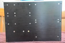
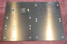
Berd's Build - Chassis bottom
Jim (6L6):
You asked for lots of pictures so here we go.
The first set are some chassis basics from a couple of weeks ago.
My goals for the chassis are:
- Use an enclosure that does not look out of place with existing Pass Labs gear.
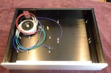
- Use a single enclosure due to space limitations in the equipment rack. I will likely need to add shielding to minimize hum and will make comparative measurements along the way.
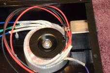
- Keep all AC wiring as short as possible and route it as far away from the inputs of the Pearl II Boards, i.e. in the right rear corner. I will keep the wiring tight against the bottom and side of the enclosure and plan to shield all AC wiring.
- Keep phono input runs as short as possible and ideally the same length. This was not possible in this enclosure so I kept the inputs on the far left and placed one channel in front of the other so that both phono inputs are far away from AC wiring.
- Keep all fastener heads flush with the bottom of the chassis.
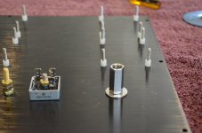
How I got it this far:
- Once I figured out roughly where all the pieces were going to be, I taped a piece of 18" x 24" graph paper to the inside bottom plate of the chassis and trimmed off the excess.
- I then laid out all the holes for mounting of the components. The graph paper lets you easily mark all the holes and check all the dimensions before drilling. It also makes it easy to get everything square relative to the edges of the enclosure, i.e. it is easy to see when two holes are not the same distance from a line on the graph paper.
- I then center punched and drilled all the holes through the paper using a drill press and a piece of scrap MDF under the bottom plate.
- Next I flipped the plate over and countersunk all the holes from the bottom while test fitting all the bolt heads (depth = diameter). The bolts become the mounting studs for the PCB's. All hardware is #6 (~ 3.5 mm) stainless steel except the #10 (5 mm) mounting studs for the transformer, grounding diode bridge and star point grounding stud (Brass).
- The transformer mounting was tricky since it uses bigger hardware. I figured out how to do it by standing in the hardware isle and trying various things. I can describe the solution if anyone wants more info.
- To hold the bolts (PCB mounting studs) in place I used internally threaded #6 x 0.250" nylon standoffs which hold the studs in place during assembly. I deliberately made the "mounting studs a bit long since I may still build a box-within-a-box later.
- I will use nylon washers and Nylock nuts on all studs once boards are finally done.
That is a good first set and I'll post more soon - comments and questions welcome.
Jim (6L6):
You asked for lots of pictures so here we go.
The first set are some chassis basics from a couple of weeks ago.
My goals for the chassis are:
- Use an enclosure that does not look out of place with existing Pass Labs gear.
- Use a single enclosure due to space limitations in the equipment rack. I will likely need to add shielding to minimize hum and will make comparative measurements along the way.
- Keep all AC wiring as short as possible and route it as far away from the inputs of the Pearl II Boards, i.e. in the right rear corner. I will keep the wiring tight against the bottom and side of the enclosure and plan to shield all AC wiring.
- Keep phono input runs as short as possible and ideally the same length. This was not possible in this enclosure so I kept the inputs on the far left and placed one channel in front of the other so that both phono inputs are far away from AC wiring.
- Keep all fastener heads flush with the bottom of the chassis.
How I got it this far:
- Once I figured out roughly where all the pieces were going to be, I taped a piece of 18" x 24" graph paper to the inside bottom plate of the chassis and trimmed off the excess.
- I then laid out all the holes for mounting of the components. The graph paper lets you easily mark all the holes and check all the dimensions before drilling. It also makes it easy to get everything square relative to the edges of the enclosure, i.e. it is easy to see when two holes are not the same distance from a line on the graph paper.
- I then center punched and drilled all the holes through the paper using a drill press and a piece of scrap MDF under the bottom plate.
- Next I flipped the plate over and countersunk all the holes from the bottom while test fitting all the bolt heads (depth = diameter). The bolts become the mounting studs for the PCB's. All hardware is #6 (~ 3.5 mm) stainless steel except the #10 (5 mm) mounting studs for the transformer, grounding diode bridge and star point grounding stud (Brass).
- The transformer mounting was tricky since it uses bigger hardware. I figured out how to do it by standing in the hardware isle and trying various things. I can describe the solution if anyone wants more info.
- To hold the bolts (PCB mounting studs) in place I used internally threaded #6 x 0.250" nylon standoffs which hold the studs in place during assembly. I deliberately made the "mounting studs a bit long since I may still build a box-within-a-box later.
- I will use nylon washers and Nylock nuts on all studs once boards are finally done.
That is a good first set and I'll post more soon - comments and questions welcome.
Attachments
-
 Pearl II Build (1) - L_Res.jpg156.7 KB · Views: 401
 -
 Pearl II Build (7) -L_Res.jpg186.7 KB · Views: 218
 -
 Pearl II Build (6) - L_Res.jpg320.3 KB · Views: 218
 -
 Pearl II Build (5) - L_Res.jpg191.7 KB · Views: 390
 -
 Pearl II Build (4) - L_Res.jpg175.4 KB · Views: 395
 -
 Pearl II Build (3) - L_Res.jpg144.8 KB · Views: 404
 -
 Pearl II Build (2) - L_Res.jpg243.2 KB · Views: 408
Last edited:
In my world that's more than a start. What you've completed is my second least favorite part of the build (least being sourcing parts). I find populating boards enjoyable and that momentum carries me through wiring.
Nice work!
Nice work!
Berd's Build - Rear Panel and U-PSU
Catching up to where the build is now...
Back Panel:
One of my goals for the chassis was to keep the AC runs as short as possible.
This plus spacing impacted the choice and mounting of the AC input jack / filter.
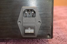
In looking at pictures of Pass XP Preamps online I figured out which AC line filter they used, i.e. a Qualtek part.
Pass used a separate line filter and fuse but I found an all in one Qualtek part at Mouser that has an AC input jack, an on/off switch, fuses, and an AC filter.
The dimensions were critical as there is not much space (front to back) in the enclosure for all this stuff.
@ 6L6: I know, I know, just outboard the supply and there is plenty of room 😀
I could not find an AC input / line filter that fit until I started thinking in three dimensions.
I figured out that if I flipped the filter upside down then the power tabs could fit in the space over the top of the transformer.
This also has the benefit of helping to keep the ac leads very short.
The next challenge was that the enclosure already came with an AC input jack and the spacing between the existing mounting holes was almost but not quite the same width so drilling holes would be tough
I decided to offset the AC line filter downward to the bottom of the back panel so I could drill the mounting holes in the right place without having the drill wander into the existing holes.
- In hindsight I could have made horizontal slots instead of holes but as the old saying goes "hindsight is 20/20"
I cut the square cutout with a jig saw with a fine tooth metal blade then filed the hole to final fit.
The hole is a bit rougher than it could be but it is smooth enough and is not visible once the filter is in place.
One bummer which happened when cutting the hole...
Although a put masking tape on the back panel before cutting it, some chips got under the jig saw base and scratched the black anodizing on back panel.😱
Note to self: In the future use multiple layers of masking tape on parts when using a jig saw.
For now, I used black permanent marker to hide scratches that, thankfully, no one but me will ever see.
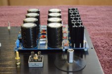
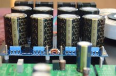
DIYAudio UPSU boards:
A couple of comments on the UPSU boards:
1) I already had them and they are great for PSU's
2) Yes, it is massive overkill but nothing succeeds as well as massive overkill
3) Read 6L6's build thread carefully so you don't have to desolder the diode legs that are in the wrong place.😱
4) Thermal compound gets everywhere on a good day and even farther when you have to do it twice.
5) I used fully insulated case diodes so no mica insulators were needed.
Jim suggested I use all the ground jumpers between the two boards to keep the ground planes at the same voltage, i.e. a low impedance between them.
The UPSU's have six pairs of holes for ground connections.
- Two sets of holes are larger than the others so I used a bare copper ground wire from some #12 Romex - I think it is AWG #14 (~ 2 mm^2).
- The other four sets of holes are smaller and are made for spade terminals. For the smaller holes I used some AWG#18 (~ 0.8 mm^2) magnet wire and scraped the insulation off with a razor knife before soldering. Solder will not stick to the insulation on magnet wire.
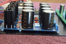
-The pads for the jumpers down between the caps are very close to the caps. If you have 35mm diameter caps it would be easier, and you would have less chance to damage the capacitors, to wait to solder the two caps that are closest to the jumpers until after the jumpers are in place.
After I finished cleaning off all the flux off the UPSU boards I realized there are actually three more pairs of ground holes behind the terminal blocks.
I am choosing to ignore them for now.
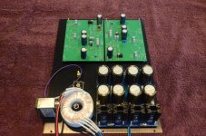
Pearl boards (Part 1) :
Normally I would wait and then stuff the boards starting with small stuff and going to larger stuff.
First resistors, then small caps then large caps, then heatsinks, etc.
Due to some delays in getting some parts, and a deep need for instant gratification, I chose to stuff the parts I already had.
I do have all the active parts but those go on last - no matter what.
The" hopefully" last shipments of parts should come in this week from Canada and the UK so next weekend should be pretty productive.
Catching up to where the build is now...
Back Panel:
One of my goals for the chassis was to keep the AC runs as short as possible.
This plus spacing impacted the choice and mounting of the AC input jack / filter.
In looking at pictures of Pass XP Preamps online I figured out which AC line filter they used, i.e. a Qualtek part.
Pass used a separate line filter and fuse but I found an all in one Qualtek part at Mouser that has an AC input jack, an on/off switch, fuses, and an AC filter.
The dimensions were critical as there is not much space (front to back) in the enclosure for all this stuff.
@ 6L6: I know, I know, just outboard the supply and there is plenty of room 😀
I could not find an AC input / line filter that fit until I started thinking in three dimensions.
I figured out that if I flipped the filter upside down then the power tabs could fit in the space over the top of the transformer.
This also has the benefit of helping to keep the ac leads very short.
The next challenge was that the enclosure already came with an AC input jack and the spacing between the existing mounting holes was almost but not quite the same width so drilling holes would be tough
I decided to offset the AC line filter downward to the bottom of the back panel so I could drill the mounting holes in the right place without having the drill wander into the existing holes.
- In hindsight I could have made horizontal slots instead of holes but as the old saying goes "hindsight is 20/20"
I cut the square cutout with a jig saw with a fine tooth metal blade then filed the hole to final fit.
The hole is a bit rougher than it could be but it is smooth enough and is not visible once the filter is in place.
One bummer which happened when cutting the hole...
Although a put masking tape on the back panel before cutting it, some chips got under the jig saw base and scratched the black anodizing on back panel.😱
Note to self: In the future use multiple layers of masking tape on parts when using a jig saw.
For now, I used black permanent marker to hide scratches that, thankfully, no one but me will ever see.
DIYAudio UPSU boards:
A couple of comments on the UPSU boards:
1) I already had them and they are great for PSU's
2) Yes, it is massive overkill but nothing succeeds as well as massive overkill
3) Read 6L6's build thread carefully so you don't have to desolder the diode legs that are in the wrong place.😱
4) Thermal compound gets everywhere on a good day and even farther when you have to do it twice.
5) I used fully insulated case diodes so no mica insulators were needed.
Jim suggested I use all the ground jumpers between the two boards to keep the ground planes at the same voltage, i.e. a low impedance between them.
The UPSU's have six pairs of holes for ground connections.
- Two sets of holes are larger than the others so I used a bare copper ground wire from some #12 Romex - I think it is AWG #14 (~ 2 mm^2).
- The other four sets of holes are smaller and are made for spade terminals. For the smaller holes I used some AWG#18 (~ 0.8 mm^2) magnet wire and scraped the insulation off with a razor knife before soldering. Solder will not stick to the insulation on magnet wire.
-The pads for the jumpers down between the caps are very close to the caps. If you have 35mm diameter caps it would be easier, and you would have less chance to damage the capacitors, to wait to solder the two caps that are closest to the jumpers until after the jumpers are in place.
After I finished cleaning off all the flux off the UPSU boards I realized there are actually three more pairs of ground holes behind the terminal blocks.
I am choosing to ignore them for now.
Pearl boards (Part 1) :
Normally I would wait and then stuff the boards starting with small stuff and going to larger stuff.
First resistors, then small caps then large caps, then heatsinks, etc.
Due to some delays in getting some parts, and a deep need for instant gratification, I chose to stuff the parts I already had.
I do have all the active parts but those go on last - no matter what.
The" hopefully" last shipments of parts should come in this week from Canada and the UK so next weekend should be pretty productive.
Attachments
-
 Pearl II Build (23) - L_Res.jpg190.9 KB · Views: 153
 -
 Pearl II Build (22) - L_Res.jpg173.6 KB · Views: 157
 -
 Pearl II Build (21) - L_Res.jpg256.8 KB · Views: 181
 -
 Pearl II Build (20) - L_Res.jpg303.7 KB · Views: 178
 -
 Pearl II Build (13) - L_Res.jpg178.2 KB · Views: 143
 -
 Pearl II Build (12) - L_Res.jpg197.8 KB · Views: 144
 -
 Pearl II Build (11) - L_Res.jpg121.8 KB · Views: 150
 -
 Pearl II Build (10) - L_Res.jpg240.4 KB · Views: 190
Such massive PSU and such close to Pearl boards will induce hum, especially at high gains. Best to put Pearl and PSU in separate boxes. Or place thick steel (iron) panel between PSU and Pearl.DIYAudio UPSU boards:
A couple of comments on the UPSU boards:
1) I already had them and they are great for PSU's
2) Yes, it is massive overkill but nothing succeeds as well as massive overkill
3) Read 6L6's build thread carefully so you don't have to desolder the diode legs that are in the wrong place.😱
4) Thermal compound gets everywhere on a good day and even farther when you have to do it twice.
5) I used fully insulated case diodes so no mica insulators were needed.
6c4c:
Yes, I plan to add shielding between PSU and Pearl boards.
I will try some different approaches and post the results here.
Yes, I plan to add shielding between PSU and Pearl boards.
I will try some different approaches and post the results here.
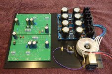
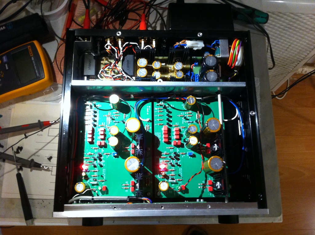
I finished to stuff the boards of my Pearl2 project. For the PSU, I used the DIYaudio store boards with MUR820 diodes and CRC filtering.


The preamp boards are pretty classical: resistors are a mix of Holco H8, IRC RC55 and Welwyn RC55; BC and Kemet MKP, Pana FC, Silmic2 and Nichicon KW electrolytics.

I also put a cap in series with R14, as suggested by Wayne:

As my current set-up (Boozhound pre+prepre) has a 70dB gain, I choose to put a 300R resistor for R14. It sould be OK, I hope.
Now, it's time to start the mechanical part of the work.
The preamp boards are pretty classical: resistors are a mix of Holco H8, IRC RC55 and Welwyn RC55; BC and Kemet MKP, Pana FC, Silmic2 and Nichicon KW electrolytics.
I also put a cap in series with R14, as suggested by Wayne:
As my current set-up (Boozhound pre+prepre) has a 70dB gain, I choose to put a 300R resistor for R14. It sould be OK, I hope.
Now, it's time to start the mechanical part of the work.
Berd- make sure the input side of the Pearl PCB are as far from the transformer as possible. One needs to be turned the other way round. The closer the input Jfet are to the transformer the more it will pick up hummmm
Folkdeath95 - the resistors in the CRC filter are an appropriate value for a power amp. For the pearl you could use one 10ohm resistor. If you don't want to buy a new resistor, remove three of the four 0.47ohm you have and just use a single 0.47ohm . That will give better noise filtration.
Also, remember to tie the centers of the PSU boards together to make PSU ground, the pearl 2 requires a bipolar supply, not a single voltage like the original Pearl.
I put transformer into separate box, attached to the back panel and I devided Pearl boards and PSU by 2mm steel panel.
But little hum still coming, because gain is 65dB and I planning to put transformers into "wall brick" case and plug it as far as I can. Magnetic fields - is real problem!
But little hum still coming, because gain is 65dB and I planning to put transformers into "wall brick" case and plug it as far as I can. Magnetic fields - is real problem!
I thought you used 10ohms resistors because you needed more voltage drop with your 30V tranformer. For the time being, I'll remove 3 resistors.Folkdeath95 - the resistors in the CRC filter are an appropriate value for a power amp. For the pearl you could use one 10ohm resistor. If you don't want to buy a new resistor, remove three of the four 0.47ohm you have and just use a single 0.47ohm . That will give better noise filtration.
I'll need to order parts to Mouser in a few weeks to recap a SP10, so I'll add 10ohms resistors to my basket.
Thanks for your help.
That's planned. I'll solder jumpers.Also, remember to tie the centers of the PSU boards together to make PSU ground, the pearl 2 requires a bipolar supply, not a single voltage like the original Pearl.
I didn't plan to separate the positive and negative voltage boards, but the PCB arrived at home like this, probably because it was easier to put it in an envelope when "broken" in two.
I found 1R/4W resistors at home, so I soldered one instead of the four 0.47R.

Thanks again 6L6 for pointing my mistake.
Thanks again 6L6 for pointing my mistake.
That will work well!
Also great you used something you already had. 🙂
SP-10? Wonderful! I'm so incredibly happy with mine I can't say enough. It's absolutely, positively the most incredible turntable, perhaps ever. 😀
Also great you used something you already had. 🙂
SP-10? Wonderful! I'm so incredibly happy with mine I can't say enough. It's absolutely, positively the most incredible turntable, perhaps ever. 😀
Jim:
Good catch on the orientation of the Pearl Boards.
This was just a quick picture and I did not notice one the boards was rotated.
Yes, my plan is to have both inputs as far as possible from the transformer.
Coincidentally ??, I have an SP-10 that is in line for restoration.
I purchased it after seeing the Pass table (Wayne's ??) online somewhere and then reading your experience with yours in the Incredible SP-10 thread.
That one has to wait a bit until I finish the couple of projects I already have in process.
My wife is patient and understanding but there are unspoken rules around the number of unfinished projects I have open at once.
Speaking from long experience I am close the the limit 🙂
I hope to "finish" one this weekend.
Carry on with the Pearl and then dive right into the SP-10!
I think the Pass SP-10s are mainly the brainchild of Cyclotron Guy (Kent) and Desmond. Wayne did a PSU, I'm lucky enough to have had one of those PCB find a good home powering my table.
I think the Pass SP-10s are mainly the brainchild of Cyclotron Guy (Kent) and Desmond. Wayne did a PSU, I'm lucky enough to have had one of those PCB find a good home powering my table.
Folkdeath:
You mentioned the cap in series with R14 as Wayne recommended.
What was the value of the cap and what was the rationale to add it ?
Can you point me to the post(s) where this was discussed ?
Sorry for asking questions that are covered elsewhere but I looked back through the thread and could not find it.
- Home
- Amplifiers
- Pass Labs
- Pearl Two