Pass DIY Addict
Joined 2000
Paid Member
Thanks for sharing these results! I have reduced the gain of each stage by itself, but haven't tried reducing both stages at the same time with my cartridge (AT 150MLX with 5mV output).
Eric
I reduced the second stage, and then both stages
I have not yet done only the first stage.
Perhaps this weekend I will be able to try only the first stage with reduced gain.
I'll let you know if I do and what I hear.
I reduced the second stage, and then both stages
I have not yet done only the first stage.
Perhaps this weekend I will be able to try only the first stage with reduced gain.
I'll let you know if I do and what I hear.
Finally had some free time since finishing the power supply so I did all the cutouts for the Pearl case.
 [/URL][/IMG]
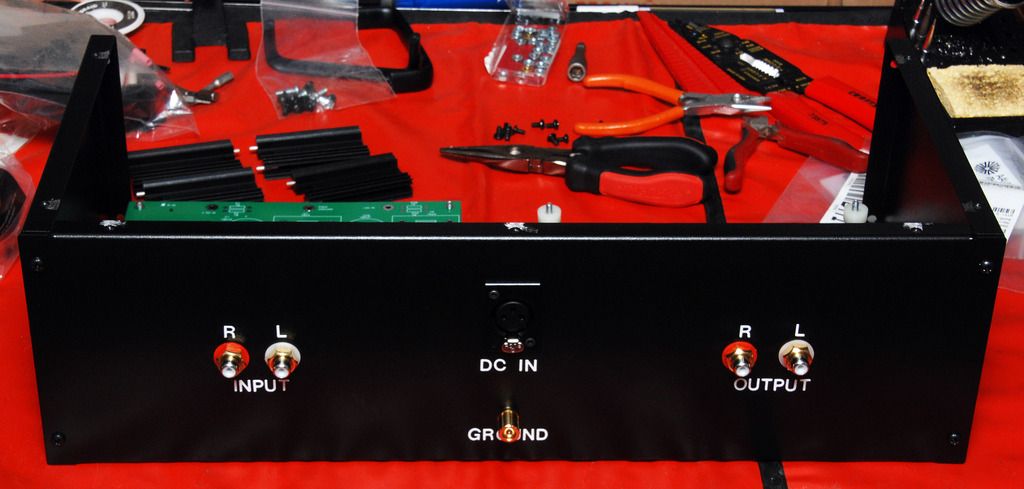
The little platform is so I can always make changes or replace parts on the boards without having to remove them. I'll mount both boards and build them as time permits right in the case. I can just remove the top & bottom covers to work on the boards. I have most of the parts and hope to get started stuffing the boards this weekend.
Bob
Pass DIY Addict
Joined 2000
Paid Member
What a GREAT idea - wish I thought of that 15 years ago 🙂I can just remove the top & bottom covers to work on the boards.
I also recommend following Jack's advice of using the female sockets in various places for easy swapping of parts.
Thanks Eric & Jack.
I started stuffing the boards over the weekend. 1st thing I installed were a few sockets for cartridge loading at C15 & R20.
I always hated having to remove boards and start removing wires to make changes or repairs so I started building everything like this with the platform. The only disadvantage is the case needs to be a little deeper. But I find it worth the trade off. If your good with metal, you could make the platform out of steel to keep it really thin and still be strong. I'm not so good with metal, so I use wood. I did have one platform made for me out of steel years ago and it's really nice. But it's a lot less expensive for me to make one out of wood and the deeper case is under $10 extra.
Best Wishes to All,
Bob
I've been slowly stuffing the boards and started reading the transistor values of my 12 Jfet's. The readings are as follows :
1 @ 7.06 ; 1 @ 7.08 ; 2 @ 7.09 ; 1 @ 7.10 ; 2 @ 7.11 ; 1 @ 7.12 ; 2 @ 7.14 ; 1 @ 7.15 ; 1 @ 7.17
I was wondering with these values, would there be a preferred way to combine them for the pair and quad in each channel?
My thoughts were to use the 2 -7.14 as the pair in one channel and the 2-7.11 as the pair in the other channel.
For the quads I would use the 2-7.09 plus the 7.10 and 7.15 in one channel and the 7.06, 7.08, 7.12 and 7.17 in the other channel. I would imagine it doesn't matter what position each is in in the quads.
Just wanted to be sure there might not be a better arrangement.
Thanks, Bob
It honestly won't matter, those are pretty darn close in general.
I'd use the .08/.09/.09/.10 in one and the .12/.14/.14/.15 in the other.
Trying to get a good and even spread across both channels ins't the goal, getting the 4 current sharing transistors as close as possible (I.E., in one channel) is much more important.
That they won't be "even" channel to channel is irrelevant. (and again, you could use any of your Jfet in any position and not worry about it at all) 😀
Hi Everyone. It looks like I have a problem 🙁 with one channel and I was wondering what might be the possible parts to replace to solve it. I finally received the parts I needed to finish up the boards yesterday and wired up the boards today. I hooked it up through the bulb tester and the bulb went out as it should. So I hooked it up directly and started to adjust DC offset.
The right channel set up perfectly and I was able to set the DC offset without a problem. It fluctuates between .5 and 6 mv which seems pretty good. If I move away from it with my body, it stops fluctuating as much and stays between .5 and 2.6 mv. The left channel is the problem 😕. The DC offset voltage is -23.68 VOLTS and stays there no matter how I set P1. No matter how I turn it, there's no effect. Also, the LED is slightly less bright than the right channel LED and goes out quicker when I turn off the power. There doesn't appear to be any shorts and nothing appears to be smoking or overheating. I imagine the bulb on the bulb tester would have stayed lit it there was a short. The voltage coming out of the regulators to the board are -23.98v and +23.94v. So the DC offset voltage for the left channel is only .3 volts less than the - voltage to the board. Any help would be greatly appreciated. While I can follow a schematic and see what connects to what, I know nothing about designing circuits and what parts might cause different symptoms. Any help would be greatly appreciated.
Best Wishes,
Bob
Look at the solder joints on everything in that channel.
Look for something misplaced or installed backwards.
Replace the ZVP3310
Look for something misplaced or installed backwards.
Replace the ZVP3310
Pass DIY Addict
Joined 2000
Paid Member
My first suggestion would be to remove the board, use a bright light and a magnifier, and carefully inspect all of your solder joints for errant solder bridges.
If the output is basically at the negative rail, it could be also be a broken connection to the positive rail.
Thanks for the suggestions. Much Appreciated. I went over the joints with a magnifier and checked with a multi-meter and I couldn't find any bad or shorted solder joints. I also checked the transistors and electrolytic caps and all are installed with the correct orientation and match the way they're installed on the good board. As for the positive voltage, I'm not sure where to check that. I'm getting the correct raw voltage coming in and the voltage out of the regulators reads plus 23.94 volts and minus 23.98 volts. I'm reading both with the black probe to ground. Red probe is on the end of R4 next to C4 for positive voltage and on the end of R33 closer to the center of the board for negative voltage. Is there another point I should be checking the rail voltage farther down the circuit? I'll check everything again tomorrow as it's pretty late here and I'm ready for some sleep. I'll also change ZVP3310 tomorrow. Could that being bad cause the kind of problem I'm having? The DC offset is just locked on minus 23.68 volts with P1 having no effect. And the red LED is a little less bright than the right channel red LED and goes out much quicker when I power down. 😕 I'm reading this -23.68v with the black probe to ground and the red probe clamped on to the leg of R17 closest to the center of the board. That's the same way I did the right channel. Using the clamp leaves me a hand free to adjust P1
Thanks Again. Time to go to sleep and start fresh in the morning.
Thanks Again. Time to go to sleep and start fresh in the morning.
Good morning. Hope your all having a good weekend.
One of the things I noticed is that the LED on the bad channel is not only a bit less bright than on the good channel, but when I look closely, it's also flickering slightly. And it does go out in about half the time of the LED on the good channel when I power down, about 4 seconds for the bad one and 9 seconds for the good one. I just started looking over the board again today and I can't find anything backwards. I'm checking all the joints with a meter. I'm using the schematic to check if the component shows continuity to the next component it should be connected to and that their not shorted to another part. So far I can't find any bad connections, but I'll check everything at least twice. All parts that are directional are definitely oriented properly and exactly as oriented on the good board. I can check the board without removing it by removing the top & bottom of my case. The boards are mounted on a platform that puts them in the middle of the cast so I can have access to both the top & bottom of the boards without removing them. If I can't find any shorts or bad solder joints, I'll try changing the ZVP3310. Is it possible the P1 pot could be bad and if so, could that cause a problem with these symptoms? As I said, adjusting the pot has no effect. The offset voltage just stays fixed at 23.68 volts. With both top & bottom of the case off, the good channel seems to fluctuate more depending on how close my head is to it. If I connect to r17 & ground with clips and take a step back, it stabilizes under 10mv. When I move my head in close and put my hands on the probes, it starts to jump around and jumps up as high as 37mv. As soon as remove my hands from the probes and move back a little, it stabilizes again under 10 mv.
Sure hope I can figure this out. It's very frustrating. I was so happy when the right channel adjusted so easily. And then so disappointed when the left channel wouldn't adjust. I had a bad feeling about the left channel as I noticed the dimmer LED right away. 🙁😕
It's probably the 3310. They are static sensitive so use a grounding wrist strap and an soldering iron with a grounded tip.
Lots of folks here have had trouble with static and this part.
Lots of folks here have had trouble with static and this part.
Thanks Berd. That's going to be my next step as it was also recommended by 6L6. I just wanted to thoroughly check all the joints and parts to be sure everything looked to be installed properly before I started swapping out parts. I went over all the joints with a meter and magnifying goggles 3 times now and can't find any joints that aren't connected. I checked all connections against the good board and every joint appears to be connected to the same points on both boards. The only part I can't check for polarity without removing it is the LED. But if it was in backwards wouldn't it just blow and not work? Maybe I'll replace it just to be sure. All these hours of testing with the magnifier has got me bleary eyed so I'll probably wait until tomorrow to start changing out parts. Would you recommend also changing the P1 pot? When I go back over this thread, I can't find a similar problem. While quite a few builders had problems with fluctuating offset readings, I don't have any fluctuation, just a solid -23.68v (.3 volt under the regulated rail voltage of -23.98v) that never varies no matter where P1 is set. I checked all the parts values to make sure I didn't mix up anything, but everything appears to be in the right place. I'm hoping that changing out the mosfet will be the solution.
If anyone has any other suggestions or knowledge of what might cause the symptoms I'm showing, I would certainly appreciate the help. I'll swap out the mosfet tomorrow and let you all know the result.
Thanks and Best Wishes,
Bob
If anyone has any other suggestions or knowledge of what might cause the symptoms I'm showing, I would certainly appreciate the help. I'll swap out the mosfet tomorrow and let you all know the result.
Thanks and Best Wishes,
Bob
Bob
The LED would not work if it was in backwards so if it lights at all is it in correctly.
I would hold off on changing the pot until after you change the 3310.
The 0.3V offset sounds like a single junction drop across a blown transistor.
Regards,
Berd
The LED would not work if it was in backwards so if it lights at all is it in correctly.
I would hold off on changing the pot until after you change the 3310.
The 0.3V offset sounds like a single junction drop across a blown transistor.
Regards,
Berd
Hi everyone. Just wanted to thank Berd, Eric & 6L6. I swapped out the 3310 this morning and that ended up being the problem. As soon as I turned it back on I had a good feeling because the LED was bright as it should be. I set the offset without any problems . Been listening to beautiful music for about 5 hours and all seems to be OK. It sounds absolutely wonderful. I have to go out now on a bunch of appointments, but I can't wait to get home & listen to some more music. Now it's time to buy some more vinyl. I ended up soldering in the 20uF Clarity ESA film caps as the output caps as I definitely liked them over the Silmics. I'm using some .1uF RelCap polystyrene's for the bypass at C8. These were caps I had left over from when I redid the crossovers in my speakers about 7 years ago. They've been sitting in a drawer since then and this seemed like a good opportunity to finally use them.
Thanks again to all for the help & support. Very Much Appreciated. Just knowing there were so many knowledgeable people out there for support is what gave me the confidence to start this project. And listening to the results makes me glad I did. All I can say is WOW.
Best Wishes,
Bob
Thanks again to all for the help & support. Very Much Appreciated. Just knowing there were so many knowledgeable people out there for support is what gave me the confidence to start this project. And listening to the results makes me glad I did. All I can say is WOW.
Best Wishes,
Bob
Pass DIY Addict
Joined 2000
Paid Member
Awesome news! Congrats on finishing your build and solving the problem. Those 3310s sure are sensitive little buggers...
- Home
- Amplifiers
- Pass Labs
- Pearl Two