I cant see what kind of 2SK170 are in the Ono but mostly everybody used BL.
The Source resistors and voltage are also the same so I think in both Phono preamps the BL is used.
According to the service manual the gain of the MC is 31 to 36dB.
How does it come that Gain is calculated like that?
I dont understand.
I just found the difference.
The Ono has 2 x 499Ohm resistors in the cascode.
That means if we use the BL version in this circuit the gain wont be the same as in the Ono.
As you said BL and GR have a different transconductance.
Just to summarize, the different alternatives we discussed are the following:
1. which version of 2sk170
2. Gain reduction jumpers
3. Caps: 220uF/ film 10uF
4. Cascode (is 2SC1844 available or we should go to ztx450 like in the Pearl)
5. Usage or not of the inverter buffer
And my opinion is the following:
1. I think it will finally depend on what is available. Many people have built the Ono successfully using the BL version.
2. Gain reduction jumpers: the change that was proposing hermanv was a good solution. I vote for it (although I might use different values for the resistors)
3. Caps: I would both alternatives at least for C37
4. Is 2SC1844 available? Otherwise no need to discuss
5. Buffer: I believe that both alternatives should be tested, so I would leave both options.
Just to summarize, the different alternatives we discussed are the following:
1. which version of 2sk170
2. Gain reduction jumpers
3. Caps: 220uF/ film 10uF
4. Cascode (is 2SC1844 available or we should go to ztx450 like in the Pearl)
5. Usage or not of the inverter buffer
1. Well I only have 2SK170BL and I will be using these.
2. I like a solution like hermanv´s. How much gain reduction is needed?
What are the option from MC cartridges?
3. I dont like the 220uF cap at all. So solution from 2. is a must. I just dont know how it will work. The following resistor has to stay large. Above 47Kohm. I want to use the same 10uF cap like in the Pearl.
4. I also want to use ZTX450 because I have a lot of them. I think this is not so important because its a normal transistor. btw is the ZTX450 a low noise one? because we could also use a Europian part like the BC550 or BC560.
5. I would use the buffer because the phase will be inverted but maybe we could have the option to bypass it.
I did some simulations of the described circuit.
I used 10 uF for c37 and c19. I did two simulations, one for an input signal of 0,5 mV and 1KHz and the second 2 Hz.
I used 10 uF for c37 and c19. I did two simulations, one for an input signal of 0,5 mV and 1KHz and the second 2 Hz.
About the MC stage I didnt have any time free to work on it.
I have a lot to do till January.
About PCBs and parts.
I get a lot of questions and requests and I would like to say to all who are interested that I still have a a few of them left.
I have a lot to do till January.
About PCBs and parts.
I get a lot of questions and requests and I would like to say to all who are interested that I still have a a few of them left.
Hello Xavier1000:
Sorry to answer so late, but promethius also seems currently unavailable.
Please clarify when you say it doesn't seem to be working properly. It is hard to tell because the input is small. but if the input signal is the same amplitude at 1Khz and 2 Hz, the output seems to be down about 6 dB at 2 Hz. Isn't that in the range of what is wanted? (I was trying for 3 dB at 5Hz if memory serves).
Did I miss something in your posts?
Hi Hermanv,
After reviewing the results of these simulations I came to the conclusion that I was not specially brilliant that day ! When I did these simulations I made two big mistakes:
The first one I was only concentrating in the fact that the signal was down when using 10 uF and not when using bigger caps, instead of thinking whether this reduction of around 6 dB could be acceptable or not at 2Hz.
The second (and far more important) is that I wasn't looking to the right signal. The non inverted output (the blue one, not the red one) is in fact almost the same for both 1Khz and 2Hz.
Xavier
After reviewing the results of these simulations I came to the conclusion that I was not specially brilliant that day !
When I did these simulations I made two big mistakes: The first one I was only concentrating in the fact that the signal was down when using 10 uF and not when using bigger caps, instead of thinking whether this reduction of around 6 dB could be acceptable or not at 2Hz.
The second (and far more important) is that I wasn't looking to the right signal. The non inverted output (the blue one, not the red one) is in fact almost the same for both 1Khz and 2Hz.
Xavier
Hi Xavier;
We all have those days, more often as we get to be my age.
It is desireable to have a roll-off above the record warp frequency with (two warps) this would be about 1 Hz and above the tonearm resonance frequency which varies from anywhere in the 1 to 10 Hz range.
The blue traces are all but invisible on the posts (at least on my monitor).
It seems that the circuit is working more or less as was intended, now comes the hard part, building and most importantly listening.
Cant we somehow get rid of C37?
Isnt it possible to bias the Fets so that we can get them working without the coupling cap.
Its just that we have too many caps in the signal path.
The MC of the Ono had Electrolytics there but anyway its just a question.
Isnt it possible to bias the Fets so that we can get them working without the coupling cap.
Its just that we have too many caps in the signal path.
The MC of the Ono had Electrolytics there but anyway its just a question.
Getting rid of C37 might be possible by biasing the source of Q15 with a resistor up to the emitter of Q24 (the parallel value of the new R with R50 should still equal 56 Ohms). We also need to verify Q24 can carry the extra load.
Two things will happen, one is headroom on the drain of Q15 will be compromised I do not know by how much (I haven't simulated the design) and you will give up a roll-off corner.
It's a judgement call if this ends up better or worse for the final design.
Two things will happen, one is headroom on the drain of Q15 will be compromised I do not know by how much (I haven't simulated the design) and you will give up a roll-off corner.
It's a judgement call if this ends up better or worse for the final design.
Hi Promitheus,
I tested the circuit, but without the output buffer, and I did some tunning. The final result was very good.
After building the original circuit, my initial impression was that the circuit was too noisy.
I changed the cascode to a BC547c which, according to the datasheet had better figures. Although there was some improvement, the noise was still too high. The next thing I tried was to reduce the voltage at the drains of the jfets by using 5k instead of 10k for R16. The results were quite promising, but then the cascode was running too hot. In order to reduce Vce of the cascode, I changed the point where I was getting the supply from the Pearl. I took the lines from C8 (24.2v) instead of C15 (28.8v) from the Pearl, having then an additional filtering.
I also changed the source resistors from 22R to 10R to have a little bit more gain and less noise. I put a dip with 2 gain positions: 21dB and 27dB.
I've been testing this circuit for a while and the result is really good, and very quiet.
I attached the final MC stage that I am currently using.
Xavier
Attachments

I forgot to mention that I am currently working in an output stage for the Pearl for converting to balanced operation. I attached a block diagram of the whole phonostage.More info in this thread
Phono amp be it pearl or Ono
Yes I would like two of these boards when finalised ie Pearl or Ono? I have just ordered 2sk389 and 2sk170bl from www.dalbani.co.uk at £1.75 and £0.75. plus 2sc1844 from www.visionaids.co.uk at £1.12, obviously UK vat P&P etc adds to this. Hope this is of help to potential builders
Andy
Yes I would like two of these boards when finalised ie Pearl or Ono? I have just ordered 2sk389 and 2sk170bl from www.dalbani.co.uk at £1.75 and £0.75. plus 2sc1844 from www.visionaids.co.uk at £1.12, obviously UK vat P&P etc adds to this. Hope this is of help to potential builders
Andy
I finished my Pearl about a week ago and it sounds great. Thanks to Promitheus for boards/parts and advice. This is my first attempt on Pass diy, very good design indeed (well I guess y'all know that). With my Rega P3 (even no ground cable), it really sings.
outto
outto
Attachments
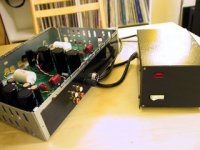
That looks great!
I didnt have any problem with the Rega either.
Its very quiet and really clear sound.
I didnt have any problem with the Rega either.
Its very quiet and really clear sound.
- Status
- Not open for further replies.
- Home
- Group Buys
- Pearl phono PCBs Group Buy