…I finally see it. (And I’ve looked at your photos quite a few times…)
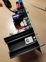
The output transistors are facing the wrong way. The text needs to face away from the red LED.


The output transistors are facing the wrong way. The text needs to face away from the red LED.

Because it’s not unusual at all?
I’m just happy to get (hopefully) one step closer to straightened out and working properly. 🙂
I’m just happy to get (hopefully) one step closer to straightened out and working properly. 🙂
Could that be, beacuse you´re still using the HI-gain setting???Dirk,
Thanks for the suggestions. I have tried the setting you specify. With that setting, the high frequencies are present, but the distortion is incredible. It sounds like an amp thrown into massive overload.
Regarding the JFETS, I have continuity, but am wondering if I may have fried the junctions by overheating during soldering.
You need to short the gain setting jumper = low gain and all dip-switches to off as a starting point. Yoru 2M has more
than high enough output as it is. Maybe you even need to alter the gain resistors according to the build guide, to get a bit
lower thn the standard 50dB, which in my opinion is on the high side,
But first: Short the gain setting jumper = low gain and all dip-switches to off.
Then we can go on from there 😉
And just to exclude other errors (how dumb they might sound), be sure, you´re using a line input in your pre/amp and NOT "Phono" ...
And.... btw.... if none has commented yet..... Your cartidge is NOT a HOMC..... It´s a MM.
Last edited:
WOW @6L6 ...... or should we call you "Hawkeye" instead?? 👍 👍…I finally see it. (And I’ve looked at your photos quite a few times…)
The output transistors are facing the wrong way. The text needs to face away from the red LED.
View attachment 1379468
View attachment 1379470
Been looking at those more than once....... and missed it.
Well spotted !!!
First, 6L6, THANK YOU VERY MUCH for spotting the error of the flipped output transistors. Given the angle I shot the photos from, I'm amazed you spotted that problem.
The good news is that after correcting the orientation of the output transistors, the distortion came down by (a guess) 75%. The bad news is that it's still very high. It appears to increase as the presence of low frequency material in the music increases. I played some high frequency sine and sweep tones, and didn't hear distortion.
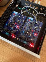
After my error with the output transistors, I went through the res too the devices to make sure they were installed correctly, and I believe they were. I've also gone through all the resistors to make sure I have the right values in the right places.
I'm beginning to feel guilty asking for more guidance, but any thoughts would be very much appreciated.
P.S. I've got R27 set to 680R to get the voltage up to .44v. I wouldn't think being at the low end of the voltage scale would cause this kind of distortion, but being at 300% of the provided resistor value seems odd.
The good news is that after correcting the orientation of the output transistors, the distortion came down by (a guess) 75%. The bad news is that it's still very high. It appears to increase as the presence of low frequency material in the music increases. I played some high frequency sine and sweep tones, and didn't hear distortion.
After my error with the output transistors, I went through the res too the devices to make sure they were installed correctly, and I believe they were. I've also gone through all the resistors to make sure I have the right values in the right places.
I'm beginning to feel guilty asking for more guidance, but any thoughts would be very much appreciated.
P.S. I've got R27 set to 680R to get the voltage up to .44v. I wouldn't think being at the low end of the voltage scale would cause this kind of distortion, but being at 300% of the provided resistor value seems odd.
Hello AkimoSD,
if you measure 0,44 V over resistor R27 (measured from one leg of resistor to the other leg of the resistor R27), this would mean
your bias is around 0,44 V divided by 680 Ohm = 0,00065 Ampere (=0,65 mA). Far too low.
The target should be anywhere between 4 to 5mA.
Have you tried the original value of 220 Ohm for R27? Or anything else is wrong.
The red LED is on? LED has correct orientation?
Greets
Dirk
@AkimoSD ...
Please respond to these questions directly.
1. Have you removed the jumpers over J1 and J2? You are using a MM cartridge and it should not be set to the 70dB setting. Yes or No?
2. Have you read Randy's explanation of setting R27 in the build manual? The purpose of a higher value resistor is to lower the current. Read and follow his instructions carefully.
3. Read BoydK's post 4384 above and make sure you have covered all of his suggestions. Are you putting the P3's output into a phono input?
This will allow us to move forward.
…I finally see it. (And I’ve looked at your photos quite a few times…)
The output transistors are facing the wrong way. The text needs to face away from the red LED.
You mean, someone else did it too? Phew....
Attachments
cubicincher,
Thanks for the correction, it was 3.08v using the 680R resistor.
Craig59,
1. I'm afraid I'm not aware of the J1 jumper. For the J2 jumper, if removed, I get distortion to the level that you almost can't hear music behind it. It also results in (as I believe is expected) much higher gain.
2. I'm really glad you pushed me on this. I found an error in my notes that took me in the wrong direction. At R27=220R, the voltage was slightly high with a lot of audible distortion. I swapped in a 330R resistor (resulting in .78V at R27), and much of the distortion is gone!
3. I had missed BoydK's post, but luckily, was not making either of the error types he listed.
I'm afraid I've run out of time for today, but I think my logical next move is to try 440R at R27.
Thanks again for everyone's guidance!
Could one of the transitors be blown because of the mounting the wrong way round? Could this explain why there is still distortion?
There is some confusion about the voltage across R27. 3.08V would mean 4.5 mA bias, nicely within the range of 2-5 mA. In that case 680R is OK. But you also mention 0.78V. Between which points did you measure that voltage?
There is some confusion about the voltage across R27. 3.08V would mean 4.5 mA bias, nicely within the range of 2-5 mA. In that case 680R is OK. But you also mention 0.78V. Between which points did you measure that voltage?
Hi AkimoSD, I don't know if this will help you, but I also run an Ortofon 2M Bronze. I only ever run it with the low gain setting, and with 47k of resistive loading. No capacitance.It's an Ortofon 2M Bronze, with the following recommended config:
load: 47k
capacitance: 150-300 pF
It's rated output is 5mV
I tried both the recommended DIP settings and a wide range of non-recommended ones (perhaps I missed the right combination), and couldn't get any upper frequencies at all. I also tried with the high output jumper in place and without it.
Attachments
What is the optimal Idss in the pearl 3? I saw some posts like the above about it but I am still confused. What would be the result of using lower or higher idss jfets?Good eye, you have to keep an eye on me. It was R8 I did the current calculations with.
E = IR, voltage drop across R8 / 10 Ohms equals total current through R8 or 12ma +/- a red curly hair.
With my pencil, paper and HP calculator it looks like with this circuit there is a voltage divider thing going on. From the reports of other members here on diyAudio it looks like we get about 41% of jfet Idss measured across R8. For your matched 2SK170 sets of 4 jfets that is 6.3ma * 4 * 0.41 gets ~= 10.33ma total current through R8.
This is right in the center of good, this is more Idss current than the GR 2SK209's that most people are using. You likely do not need to change anything.
Thanks DT
Jim: Tested 100 of the 2sk209s recently and found their IDSS values to have substantial variance -- from the high 3's to the low 5's. There is an advantage to matching a set to the same IDSS value -- BUT, further, is there an advantage to selecting a set that is on the low side of this IDSS range?
- Home
- Amplifiers
- Pass Labs
- Pearl 3 Burning Amp 2023