also...
remember, this is a "pioneer" project with all the attendant exploratory fun expected.
Perhaps the excellent "out of the box" results diminish that perception.
personal aside: I for one acknowledge and deeply appreciate all the work put in by the pioneers!
remember, this is a "pioneer" project with all the attendant exploratory fun expected.
Perhaps the excellent "out of the box" results diminish that perception.
personal aside: I for one acknowledge and deeply appreciate all the work put in by the pioneers!

Absolutely. I have a 6.5-digit Keysight bench meter, and do exactly that. With some resistors that I have plenty of stock of, I've even matched up 1% sorted resistors to 0.1% or 0.05%, or better if I'm being obsessive and have enough parts. Cuz, why not?Why not purchase an excessive number of 0.1% tolerance resistors and then hand-match those for even tighter tolerance?
Have done the SMD matching and 0.1% resistor selection described above for the B2018 preamp and found the extra trouble to be worthwhile. See posts 4357, 4361, and 4371 here:
Would add to the sage comments above that it is good to match eight 2SK209s (rather than 4) so that both boards are complementary and thus the soundstage benefits.
BTW, found that it was impossible for me to measure the 2SK209s without the Peak SOT23 Test Adapter. Not expensive but if you are going to measure 100 or so SMDs you will appreciate the (relative) ease it imparts to the job.
Any thoughts or comments on Wayne's linestage presented at BA 2018?
It looks like an economical high performance design with a couple of nice options (like a beefier output if needed)
I'm a terrible designer and a slow builder - I think we wound be interested in hearing if there are any experiences or opinions yet.
Thanks Wayne!
YouTube
It looks like an economical high performance design with a couple of nice options (like a beefier output if needed)
I'm a terrible designer and a slow builder - I think we wound be interested in hearing if there are any experiences or opinions yet.
Thanks Wayne!
YouTube
BTW, found that it was impossible for me to measure the 2SK209s without the Peak SOT23 Test Adapter. Not expensive but if you are going to measure 100 or so SMDs you will appreciate the (relative) ease it imparts to the job.
@GKTAudio:says:
"Cuz, why not?"
Good for you, GKT!
Am thinking of getting the Peak Atlas ESR70 Capacitor and low resistance tester to go along with the Peak DCA75 component analyzer currently in use. My Fluke 115 doesn't measure low value resistors well.
"Cuz, why not?"
Good for you, GKT!
Am thinking of getting the Peak Atlas ESR70 Capacitor and low resistance tester to go along with the Peak DCA75 component analyzer currently in use. My Fluke 115 doesn't measure low value resistors well.
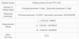
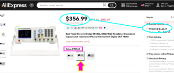
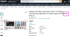
I use my East Tester ET4510, which I bought from AliExpress, to measure very small resistances. It ships with very nice four-point Kelvin probes, which increases accuracy in the below-one-ohm domain. It's also great for discovering the self resonant frequency of electrolytic capacitors . . . . . which allows you to immediately calculate the self inductance "ESL". Amazon sells it too, at a higher price of course. Here are the specs from their sales page
_
_
Attachments
Another technique to measure low value resistors (and DC resistance of chokes) is to drive them with a 1.0 Amp current source, while measuring the voltage.
@TungstenAudio: recently blew up my Mackie 1604 mixing board and disassembled it to see if there was anything fixable. Several large caps in the PSU appeared suspect as well as two diodes. Took them out and tried to measure them. My Fluke 115 measures some caps but not larger ones apparently. The diode checked out OK. Online sources suggested your current source method and there was a method for checking the cap to about 67%. Need to learn a bit here.
Put it all back together and "voila." It works again -- for no reason I can ascertain.
So, as always, the good news is I can buy another mixer -- am going with a Neve summing mixer instead. It fits my analog recording (4-channel tape mixed down to 2 channels for dissemination) better and offers the option of inserts (for analog reverb). All stays class A. All stays balanced.
@Mark Johnson : Is this the one?
https://www.aliexpress.us/item/3256...ccJzGt5C&utparam-url=scene:search|query_from:
always looking for a new box and it is less than Amazon.
https://www.aliexpress.us/item/3256...ccJzGt5C&utparam-url=scene:search|query_from:
always looking for a new box and it is less than Amazon.
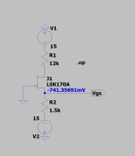
On the next batch of boards, would suggest that some "pads" and resistors for a SOT23 test device. Can be readily fashioned to measure Idss. The method was shown in Sam Groner's excellent article "A Low Noise Laboratory Grade Measurement Laboratory Amplifier", in Linear Audio. For those of you who hadn't subscribed the schematic is shown below. Measure where shown, using an insulated tweezer to place the JFET on the jig. matching to +/- 20% should suffice.BTW, found that it was impossible for me to measure the 2SK209s without the Peak SOT23 Test Adapter. Not expensive but if you are going to measure 100 or so SMDs you will appreciate the (relative) ease it imparts to the job.
Attachments
Yes, thanks for mentioning the Kelvin probes - they are important for accurate and sub-Ohm readings. Also important to null out the meter first. Also, I use my Tonghui TH2832 LCR meter with the appropriate Kelvin test jig which gives excellent results with, well, L, C and R components. 🙂I use my East Tester ET4510... It ships with very nice four-point Kelvin probes,
Yes, and I've been doing that since getting an HP DC current source, and a Keithley 224 programmable DC current source last year (when I'm feeling particularly motivated).drive them with a 1.0 Amp current source, while measuring the voltage.
It's amazing what you learn about component characteristics once you get accurate, relevant measurements with good test gear. But do you need it all to build an excellent Pearl 3? Nay, nay, I say. Optimizing one link in the audio chain will motivate one to do the same along the entire chain, however. All good fun and rewarding.
@meanman1964: Don't think so. The problem is that after install and adjustment you are not completely certain of the active ohms value, you can't figure the actual current using Randy's formula. The only time this would work would be if you measured the pot before install and used that value for the mA computation afterwards. If you setup a mounting system where the trimpot could be moved in and out of the PCB then you could, I suppose, get a very accurate current value. Believe that someone above has suggested this cannot work (6L6?).
I don’t think I said it couldn’t work, but I would not suggest it.
Adjusting the R27 resistor value is not critical and should be considered optional on all builds. However if you want to change it, please do, it’s fun.
Buy a resistor kit similar to this - it is very useful and will serve many projects in the future.
https://a.co/d/7XqDRpl
Adjusting the R27 resistor value is not critical and should be considered optional on all builds. However if you want to change it, please do, it’s fun.
Buy a resistor kit similar to this - it is very useful and will serve many projects in the future.
https://a.co/d/7XqDRpl
I just completed wiring things up, and I'm hoping for a bit of troubleshooting advice. I'm getting signal through both channels, but there appears to be a fierce rolloff in the upper frequencies. My cartridge is a HOMC so I've set the DIP as such and experimented with other settings to no avail. I rechecked the component values in the passive section of the RIAA filter, and they appear to be to spec.
I'd be grateful for any guidance.
P.S. As background, I'm not an engineer. I haven't done a DIY audio project in about three decades so I'm probably missing something very obvious and extra stupid.
I'd be grateful for any guidance.
P.S. As background, I'm not an engineer. I haven't done a DIY audio project in about three decades so I'm probably missing something very obvious and extra stupid.
Thanks for the very quick response. I should have also mentioned the following:
1. The problem is occurring in both channels, so I'm assuming it's not a single, faulty component.
2. I suspect this is unrelated, but, I have a medium level of hum specific to one channel. I've confirmed that all case panels have continuity to all others so I suspect it's something else I've done. I have a significant old- man tremor in both hands and my soldering is pretty ugly these days.
Attachments
It's an Ortofon 2M Bronze, with the following recommended config:
load: 47k
capacitance: 150-300 pF
It's rated output is 5mV
I tried both the recommended DIP settings and a wide range of non-recommended ones (perhaps I missed the right combination), and couldn't get any upper frequencies at all. I also tried with the high output jumper in place and without it.
load: 47k
capacitance: 150-300 pF
It's rated output is 5mV
I tried both the recommended DIP settings and a wide range of non-recommended ones (perhaps I missed the right combination), and couldn't get any upper frequencies at all. I also tried with the high output jumper in place and without it.
- Home
- Amplifiers
- Pass Labs
- Pearl 3 Burning Amp 2023