
Hello All,
I have been poking around with this thing and scratching my head.
There is only a bit of voltage drop across the NPN transistors. Most of the 15Volt supply voltage is divided between R1 and the JFETS. The more current the JFETS draw the greater the voltage drop is across R1 which leaves less voltage to drop across the Jfets. A bit of circular thinking I know. Looking at it as a voltage divider does offers some insights.
Tonight I dug into my secret stash of 2SK170 BL's, and found 8 JFETS with an IDSS of near 0.0067 Amps each. With 4 of these my guesstimate is that the P3 input stage will draw about 11 or 12ma. These JFETS are going into the Pearl 3 PCB's received at Burning Amp.
I received a package from Mouser that contains LM7815's and LM7915's. Next is a breadboard with a LM7815 to power the P3 input stage breadboard.
Thanks DT
Why?Or start a new thread featuring his own phono preamp design, applying all of the knowledge he’s acquired in his experience.
This is the thread for discuss the new offer: PEARL 3. I am always interested in the circuitdesign of others, that is the only reason why i am appeard. I like Mr. Colburns approach to make the community happy ...
Last edited:
There is a reason why Pearl 1 runs at approxy 30Volts, not only why the span between -15V and +15V (the current rails) is 30V. It's all very basic knowledge on primary (school) level.
Bye,
must leave now (before i get a penalty from the lovely moderator).
Bye,
must leave now (before i get a penalty from the lovely moderator).
Last edited:
"There is only a bit of voltage drop across the NPN transistors." [quote DT] You know the expression, the word 'voltage drop' ("Spannungsabfall, bzw. Spannungsfall, Potentialdifferenz"), i am happy. One person (pretend to) don't know it.
UCE about 2V is ok. In Pearl 1 it is higher.
Now we can talk about CascodeOperation! But we don't have to.
UCE about 2V is ok. In Pearl 1 it is higher.
Now we can talk about CascodeOperation! But we don't have to.
Last edited:
Starting to get a bit annoying 😅
Anywho, anyone know of a good smd replacement for output pair? 🙂
Anywho, anyone know of a good smd replacement for output pair? 🙂
@hbtaudio
I’m inspired to ask a simple question.. it needs no response please.
With all the knowledge and insight that to me seems apparent you have—why not design a phono circuit for all of us to properly benefit from your ideas?
Seems so simple to me. I for one would build it… just like i’m building Wayne’s generous offering..
Come back when you have a link to your project. I will be the first to build it…. and evaluate how it SOUNDS to me in my high end system against at least 4 other preamps….all from extremely knowledgeable designers. Peace.
Anywho, anyone know of a good smd replacement for output pair? 🙂
I saw Accuphase using 2SC6124 / 2SA2206 in their more recent designs, alongside the TTA004 / TTC004. Probably depends on bias current / heat dissipation.

Many posts deleted.
hbt audio will not be posting in this thread for a while.
Too late. You were warned earlier.Bye,
must leave now (before i get a penalty from the lovely moderator
Last edited by a moderator:
I was hoping that I could just use my P 2 PS for the time being.
No worries, you absolutely can.
The Pearl 3 needs bipolar DC on it’s power inputs, just like Pearl 2, and those onboard regulators will do their job and make +/-15v for Pearl 3.
Given the higher raw rail voltage for the Pearl 2, one can afford to burn a few volts before getting to the Pearl 3 PCBs. I am thinking of something simple like CRC.
A related question:
I've been playing around with various configurations. One has the boards arranged back to back, signal jacks at one end, power at the other with the potential to stand the enclosure up vertically, signal jacks out the top. I actually have a biscuit box with the right size (4"x4"x9") and configuration.

I'm wondering about heat management. I expect that the heat generated by the regulators will depend on the input voltage. What's the minimum input voltage that won't compromise the performance? Or do these need to be "toasty"? The orientation of the heatsinks won't be ideal. Does that matter? Would I need to change them or mount them horizontal to the PCB? Thoughts?
I've been playing around with various configurations. One has the boards arranged back to back, signal jacks at one end, power at the other with the potential to stand the enclosure up vertically, signal jacks out the top. I actually have a biscuit box with the right size (4"x4"x9") and configuration.
I'm wondering about heat management. I expect that the heat generated by the regulators will depend on the input voltage. What's the minimum input voltage that won't compromise the performance? Or do these need to be "toasty"? The orientation of the heatsinks won't be ideal. Does that matter? Would I need to change them or mount them horizontal to the PCB? Thoughts?
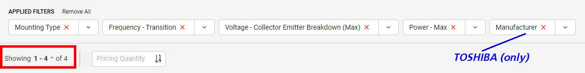
Anywho, anyone know of a good smd replacement for output pair? 🙂
DigiKey found a few; here are the parametric search parameters that worked for me.
_
Attachments
Hi 6L6, no offense intended. Here's the traduction : Thunder of Brest! Waffle pan! Drink-without-thirst! Bring me this pearl... or whiskey!This is an English language forum... Please post the translation.
In pure Captain Haddock style.
@mhenschel
Regulator input needs to be about 2v above the 15v output. Call it +/-17v or higher for the raw supply.
Regulator input needs to be about 2v above the 15v output. Call it +/-17v or higher for the raw supply.
Regulator input needs to be about 2v above the 15v output. Call it +/-17v or higher for the raw supply.
Hello,
Just looking at the LM7815 datasheet, 2 volts looks to be the dropout voltage. I will play with it a bit. 2 volts may be cutting it a bit close?
Thanks DT
@rhthatcher
Thanks. I kinda got that from the datasheet. But is there a performance hit from walking on that lower edge? Is there a sweet spot at a higher voltage?
And at some lower voltage can I dispense with the heat sinks; not worry about ventilation?
What's the current draw of the circuit (apologies if that's in the discussion... I found the video unintelligible)
If providing unregulated, go for at least +3Vin. If regulated you can cut close to +2Vin (i'd go for a bit more). There is place for solid size heatsinks om the pcb, so a little bit more V than minimum required can be dissipated for ~60mA the board draws. Yes there are drawbacks if you go below minimum +Vin, some won't even work, some will work with reduced psrr etc. (over all bad performance).Hello,
Just looking at the LM7815 datasheet, 2 volts looks to be the dropout voltage. I will play with it a bit. 2 volts may be cutting it a bit close?
Thanks DT
- Home
- Amplifiers
- Pass Labs
- Pearl 3 Burning Amp 2023