No worries about DC-offset!
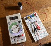
I setup the J112 circuit using 221R I had.
Voltage drop for both J112 in kit over 221R was about the same at about 2.2 VDC.
This gives about 10mA current. So I need to raise the resistor or find a JFET with lower Idss I guess.
These two in the kit have Idss = 12 mA (using DCA75 tester).
I expected much lower current than Idss. 10 mA is close to Idss. How can that happen with Vgs = -2.2V?
Did I do something wrong?
I will check circuit again when I am back home tonight. This one was a quick setup before going to work.......
Attachments

I must have measured Vgs wrong......will try again tonight 🙂
Time goes fast.......can see my "new" DMM is now at radiomuseum (but I can't blame the DMM):
https://www.radiomuseum.org/r/unknown_univolt_digital_multimeter_dt_830.html
Time goes fast.......can see my "new" DMM is now at radiomuseum (but I can't blame the DMM):
https://www.radiomuseum.org/r/unknown_univolt_digital_multimeter_dt_830.html
Hello Meper,
I also had around 10mA running through the J112 with R27 = 220 Ohm.
I increased R 27 to 470 Ohm and it is running at 5,5mA.
In my next version, I increased R 27 to 750 Ohm. I will see where I land? Target is 2- 5mV over R27.
The question about offset at the output: my first PEARL 3 is below 1mV offset - absolutely nothing to worry about.
Cheers
Dirk
DC offset will be essentially equal to the Input Offset Voltage of U1 opamp. You can roll U1 opamps to find one with least DC offset. Expect 1-2mV in case of JFET input opamp and <0.5mV for bipolar input. In my opinion, low enough in both cases to safely bypass the AC coupling cap but YMMV.
No worries about DC-offset!
I setup the J112 circuit using 221R I had.
Voltage drop for both J112 in kit over 221R was about the same at about 2.2 VDC.
This gives about 10mA current. So I need to raise the resistor or find a JFET with lower Idss I guess.
These two in the kit have Idss = 12 mA (using DCA75 tester).
I expected much lower current than Idss. 10 mA is close to Idss. How can that happen with Vgs = -2.2V?
Did I do something wrong?
I will check circuit again when I am back home tonight. This one was a quick setup before going to work.......
MEPER,
I can not see all of your connections in your photo.
Battery +, goes to Drain Pin 1,
Resistor goes between Source Pin 2, and Battery -
Gate Pin 3, goes to Battery -
Volt Meter goes across the Resistor.
Otherwise you are on the correct path.
12ma Idss is much larger than the ~4.0ma you are looking for.
Sneak up on it.
Try a 500R resistor.
Try a 1000R resistor.
The current will move closer to your target value.
Thanks DT
It seems we only need to know Idss of J112 to estimate Ids. In my case with Idss = 12 mA I end up with 10 mA using 220R. So with 220R we are looking for a JFET with Idss around 4-5 mA?Hello Meper,
I also had around 10mA running through the J112 with R27 = 220 Ohm.
I increased R 27 to 470 Ohm and it is running at 5,5mA.
In my next version, I increased R 27 to 750 Ohm. I will see where I land? Target is 2- 5mV over R27.
The question about offset at the output: my first PEARL 3 is below 1mV offset - absolutely nothing to worry about.
Cheers
Dirk
Yes, I guess if I measued Vsg correct I would find out that it was just a little bit negative (the voltage drop over 220R is not Vgs......probably my mistake). Then everything fits with J112 data sheet and the curves.........I think.....and I just have to find a J112 with Idss around 4-5 mA or use a larger resistor as you indicate.MEPER,
I can not see all of your connections in your photo.
Battery +, goes to Drain Pin 1,
Resistor goes between Source Pin 2, and Battery -
Gate Pin 3, goes to Battery -
Volt Meter goes across the Resistor.
Otherwise you are on the correct path.
12ma Idss is much larger than the ~4.0ma you are looking for.
Sneak up on it.
Try a 500R resistor.
Try a 1000R resistor.
The current will move closer to your target value.
Thanks DT
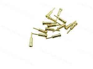
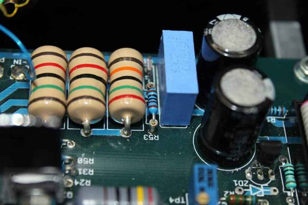
The 220R are the very very fine RN55......think there are 8 of those 220R. Not sure I in my own stock of resistors can find such a nice 470R......but I can try!
I have a bag of 100 pcs. J112 so could also try to find two with lower Idss. Maybe even a J113 could fit. I have more than 1000 of those.
MEPER,I have a bag of 100 pcs. J112 so could also try to find two with lower Idss. Maybe even a J113 could fit. I have more than 1000 of those.
That also sounds like a solution.
It would be interesting to sample some of that bag of J112's to see what Idss paired with that RN55 220R resistor operates at the target ma current.

.........
I have a bag of 100 pcs........
if you're obsessing - take one thing in account - more degenerated JFet ( of same type) is better CCS
say that you end up with 390R needed to set one JFet to desired current , and 430R to set second one
I can bet that you'll not be able to hear nor measure difference between two channels
and - there is 15V-Uled allowance there to let JFet spread its legs ......... even in dynamic conditions you'll not get even near enough to starve that JFet
I had my share obsessing with irrelevant things, doing enough of that today too, but with time I did allow people to tell me what's significant and what isn't
I mean - c'mon pple, - if you're going to steer an avalanche - either do that in threads of your own making, or at least try to produce avalanche of fun, not pure trivia, even when told how to and explained more than once
what's wrong with posting Cartoon ootoobe vids ?
much better than writing dozen of pages about source resistors for darn aux CCS or measuring caps with 15$ toy
I will find source resistors that fits the two J112 in the kit (to have better CCS). Both are quite identical with Idss = 12 mA whic is nice.
The main purpose with this exercise was to avoid to de-solder R27 resistors and think I have reach that goal. It would also have been waste of very nice RN55 resistors!
The main purpose with this exercise was to avoid to de-solder R27 resistors and think I have reach that goal. It would also have been waste of very nice RN55 resistors!
It is just camouflaged as a Lawn Mower?
The riaa will be the real thing and "grounded to earth"!
I loose self confidence every time I need to de-solder a component from a "production" PCB 🙂 ......and I am scared to destroy the solder pads....
In old days the solder pads came off with just a little to much heat!
The riaa will be the real thing and "grounded to earth"!
I loose self confidence every time I need to de-solder a component from a "production" PCB 🙂 ......and I am scared to destroy the solder pads....
In old days the solder pads came off with just a little to much heat!
For the resistor swapping, consider putting a socket in so you can swap resistors. When you find the happy resistor (I predict you'll land between 550-750R) solder the resistor into the socket.
If you do much repair work and pull a lot of soldered components - I can't say enough good things about the Hakko FR-301 removal solder gun.

If you do much repair work and pull a lot of soldered components - I can't say enough good things about the Hakko FR-301 removal solder gun.
Nice tool worth to consider a delayed Christmas present.
https://www.batterfly.com/shop/en/hakko-fr-301?search=HAKKO FR-301
I take the chance that when bias is ok on bread board it will work also at PCB.
https://www.batterfly.com/shop/en/hakko-fr-301?search=HAKKO FR-301
I take the chance that when bias is ok on bread board it will work also at PCB.
Ok, a little bit higher. I have not yet enough experience with this to know if the working point is where the curve is almost flat so current will not change much with Vds. I was assuming so......but..... 🙂
+1 if you're going to do this stuff a lot, do yourself a favor and get a proper desoldering tool. It's life changing. I do a fair amount of old gear restoration, and I make more than my fair share of mistakes. If you're already handy with soldering wick or one of those pop-suction devices, god bless you.Nice tool worth to consider a delayed Christmas present.
https://www.batterfly.com/shop/en/hakko-fr-301?search=HAKKO FR-301
I hate these sockets, they never come apart right. But... I am a big fan of being able to socket components. DIPs and transistors are easy. I am open to alternative socket choices for resistors and caps.For the resistor swapping, consider putting a socket in so you can swap resistors. When you find the happy resistor (I predict you'll land between 550-750R) solder the resistor into the socket.
If you do much repair work and pull a lot of soldered components - I can't say enough good things about the Hakko FR-301 removal solder gun.
View attachment 1258144
they never come apart right
heat them slightly and push metal part from plastic
- Home
- Amplifiers
- Pass Labs
- Pearl 3 Burning Amp 2023