For grins I have assembled on perf board a LM7815 and a Sparcos 7815 3 legged supplies.
Both supplies are operated into a breadboard of the P3 input stage.
The raw supply for both is a TRIAD 18volt DC wall wart. See the attached AP scope and FFT plots.
The LM7815 regulator is much cleaner.
Thanks DT
Orange is the LM7815 regulator.
View attachment 1248884View attachment 1248885
Could be interesting to get a comment from SparkosLabs about this result?
Can I send the result and ask?
On their web they have other results when comparing their regulator performance against "normal" 3- leg regulators.

Hello,Could be interesting to get a comment from SparkosLabs about this result?
Can I send the result and ask?
On their web they have other results when comparing their regulator performance against "normal" 3- leg regulators.
Sure send away.
Looks like 1/f noise to me.
They show this table in the data sheet and there are also some written information:

It is a 1$ device vs. a 45$ ....so a buyer would expect to get something for his money 🙂
If it is a 7812 or 7815 should nok make any difference regarding the table above.
It is a 1$ device vs. a 45$ ....so a buyer would expect to get something for his money 🙂
If it is a 7812 or 7815 should nok make any difference regarding the table above.
Me thinks that we need dedicated OCD thread in Papaland
Even if I know that (as always) I'm going to be Greataest Contributor, I'm sure rest of threads will be much less cluttered

assemble Pearl 3
put XX reg chip, measure drek on output, save
put YY reg chip, measure drek on output, save
put ZZ reg chip, measure drek on output, save
put WW reg chip, measure drek on output, save
publish saved
I'm curious what difference is going to be, knowing that cap multiplier is where it counts most
then listen most favorite option for week or so
then put decent shunt regs instead
then listen for week or so
Mighty Moi - always going ditto for last option, saving OCD for potential thread

(how much second hand vinyl can be bought for money spent on ultramegagiga custom solutions?)
Even if I know that (as always) I'm going to be Greataest Contributor, I'm sure rest of threads will be much less cluttered
assemble Pearl 3
put XX reg chip, measure drek on output, save
put YY reg chip, measure drek on output, save
put ZZ reg chip, measure drek on output, save
put WW reg chip, measure drek on output, save
publish saved
I'm curious what difference is going to be, knowing that cap multiplier is where it counts most
then listen most favorite option for week or so
then put decent shunt regs instead
then listen for week or so
Mighty Moi - always going ditto for last option, saving OCD for potential thread
(how much second hand vinyl can be bought for money spent on ultramegagiga custom solutions?)
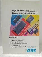
AFAIK, the original Zetex (before the Diodes acquisition) parts featured the "negative relief" style of marking - you can see it on some of their old catalogues...On another note...
I took a chance and bought some supposed ZTX851 from "littlediode_uk" on the auction site. I received them yesterday and I suspect they are fake. The other ZTX transistors I have are marked by laser etching. These are marked with negative relief paint. Compare the two photos below. Does anyone have definitive info?
View attachment 1246637
View attachment 1246641
Attachments
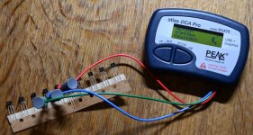
I way to get a feeling if it is a ZTX851 is to measure Vce (sat). It should be quite low because it can handle high current (5A) continuously.
With Peak instrument Vce (sat) at Ic = 5 mA was about 4 mV. It will raise to about 250 mV at 5A where max. dissipation is about 1.2 W.
With Peak instrument Vce (sat) at Ic = 5 mA was about 4 mV. It will raise to about 250 mV at 5A where max. dissipation is about 1.2 W.
Attachments
You mean by stuff like post 1,167?I'm sure rest of threads will be much less cluttered
like post 1,167?
oh, these are most welcome
It is a little hard to do the day job wondering if the timing will be right to order!
Point taken, I was attempting to add a little levity. Though I would say post 1168 is somewhat superfluous😉You mean by stuff like post 1,167?
I can relate to post 1167. I feel like a little kid waiting for Santa to arrive 🙂
I have heard from Jason that the fulfillment company lost power over the last few days and is working (as best they can) on backup generators.
…during the busiest week of the year. Which has to be awful for the company.
😕
Anyway, the kits arrived there late last week but have yet to go through their intake process, so at this point, your guess is as good as mine.
Probably not the news you wanted to hear, but things will happen eventually, so we’ll need to wait just a little bit longer…
Digikey has ZTX851STZ in stock.
STZ items are packaged on paper tape. (Cut Tape)
https://www.digikey.com/en/products/detail/diodes-incorporated/ZTX851STZ/3877360
STZ items are packaged on paper tape. (Cut Tape)
https://www.digikey.com/en/products/detail/diodes-incorporated/ZTX851STZ/3877360
Thanks, I ordered 500 pieces just now. If any Pearl 3 builders need a couple more ZTX851s , send me a PM containing a photo of yourself holding up your two PCBs and we can chat.
Hello,
Sure send away.
Looks like 1/f noise to me.
Sparkos responded back with this answer:
"yes, that is interesting as our devices should have lower noise. Im not sure where or how it was all measured, like if the regulators were measured directly or if he was just measuring the output noise at the RCA outs or something, but, if you can send a schematic of the whole unit I can take a look at it and see if there is something going on that is degrading the noise performance of the discretes."
If you have a schematic drawing I can send it back for review.
Maybe interesting for others having plans of using the Sparkos regulators for P3 build.
I myself have two sets on the way from Audiophonics in France.
If you have a schematic drawing I can send it back for review.
Maybe interesting for others having plans of using the Sparkos regulators for P3 build.
Take a look at the Pearl 3 schematic.
The measurements were taken between the collector of Q5 and ground.
A single 1000 Ohm resistor was put in the place of the jfets.
My goal was to get at look at the noise performance of the 7815 regulator working with the NPN capacitance multiplier and cascode.
The raw 18VDC supply is a TRIAD switching wall wart.
My impression is that the capacitance multiplier and 7815 do a fine job together as specified.
I do this for fun, it is like going back to the lab at school.
Thanks DT
Ok, I will send him the link to the post. Then he can look up the schematic of P3 at first post.
Maybe we can learn some new stuff from next response.
Maybe we can learn some new stuff from next response.
I think I can read from latest response that he doubt the test setup / equipment used is able to actual measure the noise from the regulators itself:
"If we try to measure the noise of the regulators directly, that typically requires a noise amplifier circuit to gain the noise up to the point that it becomes measurable.
My noise amp is home made with a gain of X1000 which is needed to get it up to the levels that oscilloscopes can measure it."
"If we try to measure the noise of the regulators directly, that typically requires a noise amplifier circuit to gain the noise up to the point that it becomes measurable.
My noise amp is home made with a gain of X1000 which is needed to get it up to the levels that oscilloscopes can measure it."
- Home
- Amplifiers
- Pass Labs
- Pearl 3 Burning Amp 2023