What does this have to do with the Pearl 3?
I tried playing an open reel with the P3 but couldn't find the capstan.
Then I put a CD on the Linn but the stylus kept skating off. If I held it in place by gently pushing inwards I got a glassy sound.
I guess antiskating for CDs has to be much higher than for LPs? Anyone know the ratio?
What gain should I set the P3 for playing CDs? Do those old Gold Master Fidelity CDs require a different curve?
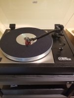
BTW, that's an old picture, that has the P2...
Attachments
Last edited:

OK.... Then let´s try this one 😛LP
I never care much about being wrong or proven so, or to stand corrected. Happens every day.
Seems, you have a different idea of the "knocking test" than most others.Garrard 301. Must be 30-35lb. It used to have felts under the plinth, if I knocked gently on the cabinet I could hear it, no more with the sorbotane hemispheres.
It´s NOT about knocking on the cabinet (of course you´ll hear that), but knocking on the platform/shelf, on whitch the TT is placed.
To test, if the knocking will go through the turntable and be hearable in the speakers.
If so = decoupling feet not up to the task 😉
@Boydk,
dude I maybe an idiot posting from my cell but I am not ret*rded!
Like I said, the sorbtane feet solve the problem for me. No adverse reactions on the sound. End of story.
And,
about the LP, I just wanted to put an end to a useless discussion in the P3 thread. I can prove the point to myself all day, everyday.
Last edited:
Nice. Thanks for bringing it back to the real world!  I was supposed to get my P3 today...the rest, as they say, is history. 🤣 Silly me for believing the tracking info!
The PS looks different. SMPS? Can you describe what was used here?
Regular chassis from Gianluca?
I was supposed to get my P3 today...the rest, as they say, is history. 🤣 Silly me for believing the tracking info!The PS looks different. SMPS? Can you describe what was used here?
Regular chassis from Gianluca?
TonyEE: Think that Mia might have found your Capstan (see below). Let me know if you'd like it back. It might be a bit wet...
Hair, hair, everywhere, not an LP to be seen.
What are those small tubed amps? I recall seeing something like that. A single ended job?
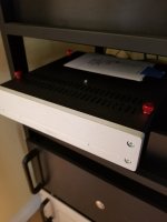
Ready to roll.. A two piece. Note I put those thumbscrews so I can move the cover easily for op am rolling. I wonder how the single power supply will fare vs the dual jobbie. The dual jobbie is bigger, has more parts and it sounds spectacular.
I guess though that if you got one of them ancient idler tables or God Forbid one of them Japanese DD, well, the single box is sufficient. But for the belt drive contingent, the more boxes, cables, sand filled stands and lights the better it will sound... I do with I had an ON/OFF switch for either side too.
I must admit though that Linn's inclusion of the phono preamp into the turntable is beyond scandalous. What next? An MP3 128 CBR encoder and bluetooth? Might as well get a Superscope turntable.
Doesn't anybody find it ironic that the P3 uses an opamp? I mean, here were going for heroics with an op amp. OK, OK, yes, it sounds extremely good and done right you can roll it... but, but, I'm afraid I won't get much respect from the local Wilson Metro$onic Audio $ociety and 250 GT SWB Motor Society. You know the type... the ones that only look at their stereo and their cars. And have the hired help clean them and polish them twice daily.
https://www.torqueo-audio.it/t34-limited/
Attachments

Last edited:
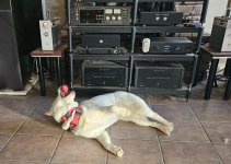
Yep. They're 300B monoblocks from Schenzen, China. Put into play because I just toasted one of the Aleph 30s normally used there. These 300Bs are very well designed and built using American and European parts; they were Douk's attempt to enter the high-end market. Failed, of course. Seems they didn't copy the original Western Electric design close enough...they are SETs and produce a hefty 10 watts per channel. Enough to blow the Tekton Double Impacts into outer space. There are more records than can be imagined to Mia's left and the Pearl 3 is right over her head. And the dog hair appears magically overnight...What are those small tubed amps? I recall seeing something like that. A single ended job?
Last edited:
Not really....... But...... if discrete SS is your game, just swap them for these or something similar 😆Doesn't anybody find it ironic that the P3 uses an opamp?
@6L6
Beautiful build.👍👍
See, the screenplate is fixed by some kind of rivet. Readymade enclosure from Gianluca??
If so......... link ??
Hey look… a Pearl 3!!
Wow! It is a single chassis Pearl 3. On the left there is an AC mains power inlet module with RFI/EMI filter, a single SMPS board carrying the MeanWell logo, and a small red PCB with several large electrolytic capacitors. On the right there are two standard Pearl 3 PCBs with voltage regulator ICs mounted on vertical heatsinks, just as Wayne designed.
So it appears to be moving coil phonostage whose AC mains power supply in inside the same chassis! Not only that, the power supply is switch mode! That is a very aggressive design and an outstanding achievement. Eureka! Congratulations!
note to readers: most SMPS boards have a single unipolar output: +19V or else -19V but not both. It appears @6L6 has discovered a MeanWell SMPS with bipolar outputs. And it must be an amazingly quiet SMPS, for him to use with a very sensitive (super high gain) moving coil phonostage.
Are you using the SE or balanced cables?
I've been using a long run of good quality SE cables... today my 10 foot Mogami/Neutrik should arrive and I intend to run the balanced outputs.
I wonder how the sound will change, if at all.
Also, will there be any deterious artifacts if I run both the SE and balanced cables to different preamps/AD/DAC. I suppose I could experiment but once things go into the rack it becomes a PITA to move around.
Guys, I could use some help. I have tried to work this out myself but don't know where else to look. I first fired up my P3 last week and it played but didn't sound good. It had a lot of distortion at med to high levels. I tried all dip switch settings and it didn't help. I checked the voltage of R27 and was getting 2.08 and 2.17V with a 220R. From what I calculated that's almost 10mA. I had a cheap box of resisters that I use for arduino projects. I changed out R27 with a 680R and when I fired it up I was getting like 1.3V across R27 and just a high pitch screeching sound. Also my LEDs on D3 would not come on. I checked the box of resisters and found they were 1/4W. I went today to a local electronics supply and got some good quality 1/2W resistors. I put some 560Rs in R27 and I'm getting the same thing. 1.4V on Right and 1.3V on left and the same screeching sound. I'm getting 22V from the power supply to the boards. Thinking I blew something? BTW I'm using a M2 Blue cartridge.
Thanks if anyone can come up with some suggestions of where to look next.


Thanks if anyone can come up with some suggestions of where to look next.
Can you post some images that are full-size? These are tiny.
1/4W resistors are fine.
If the LED isn't on something is likely installed backwards.
Don't worry, we'll help you get this figured out. 🙂
1/4W resistors are fine.
If the LED isn't on something is likely installed backwards.
Don't worry, we'll help you get this figured out. 🙂
I did have LEDs at first before I replaced the resistor at R27 and I had music, just sounded bad.


l completed the boards. They will go into this 1.5 height hammond box boards will be under mounted with nylon standoffs on the lid with in/ out rcas and gnd lug. There will be a neutrik for the ps umbilical.
I did the same for the hypnotize ad797 riaa (see photo) and that worked out well. I don’t have room for a big riaa box behind the TT and l m happy with the noise insulation provided by the hanmond box.
I only wish the boards would accommodate the good sounding Russian 1uF toilet paper in oil caps. 😉
I might play with the and lower the gain some. The hypnotize riaa gives 62db (measured) gain, even with my 0.25mv mc pickup is plenty gain for me.
Hello maxellfullmon,
what I can see on your pics - the parts seem to be oriented correctly.
What I can't see: the two TOSHIBA TTA004B and TTC004B are not mistakenly in the wrong spot? But this is impossible - then your outputstage wouldn't bias up.
The red LED is also correctly oriented - has to be or it wouldn't light up
Your bias is on the lowish side with R27 = 560 Ohm. You measure 1.3 and 1.4 V over R27, so you have 0,0023 A (2,3mA) and 0,0025 A
(2,5mA) as bias. I would change R27 to a value around 330 Ohm or 390 Ohm.
You can measure your voltages after the regulators. If you go in with around 22 V DC - this is no problem for the regulators.
Correct regulators on positive and negative side? - Should be - or it wouldn't work.
Most important for me: check soldering of JFets (Q1-Q4) - all legs in good contact?
Only some thoughts and assumptions.
Cheers
Dirk
- Home
- Amplifiers
- Pass Labs
- Pearl 3 Burning Amp 2023