And I'm running the Pearl 3 on the lowest gain setting 49db single ended and 55db gain balanced Jumper 1 closed.
Hey! 🙂☀️
This got me really curious. Step up transformers for MC pickups.
What is your take on these, has anyone of you tested it in your vinyl signal chain?
This got me really curious. Step up transformers for MC pickups.
What is your take on these, has anyone of you tested it in your vinyl signal chain?
Just sold a Rothwell MCX yesterday! Seemed pretty nice but won't need it once I finish my P3. We have/had a Cotter SUT at the store and that was quite special! Played w/ a Bryston marketed one and perhaps it wasn't broken in but that didn't compare w/ he Cotter. Unfortunately, the Cotter vanished before I could compare it w/ the Rothwell.

Forgive the case work......it's been many things in its 20 year life...But now housing the Pearl 3 dual mono as a quick and easy first 'lets see' what's all the fun is about.
IMO this Pearl 3 Phono Stage is a no brainer, I have for the past 5 years run with the Pearl 2 and very pleased with the sonic performance as it bettered most of what I tried it up against....up to 4K Rega, Exposure VXN, Dynavector IV and many others, but the Pearl 3 has beat all Ive tried.
Duel mono config 2 x 30VA 15-0-15 Txs into 30,000uF (CLCRC) no frills PSU. Sounds fantastic..used in high gain, there's no hum no hiss or strange noises just retrieves the info off the grove and presents it in a no fuss, this is what's in the grove. Clarity and detail are quite superb, lower registers are fuller and better defined along with a velvet black back ground compared to the Pearl 2 which also has the black background but not so dark.
Last edited:
Tried the P3 with Denon AU-S1 SUT in combination with Denon DL-S1. The SUT was built for this ULOMC cartridge, so it matched better. With other MC cartridges I don't have a preference. Currently using my Shure SC39ED MM cartridge (400pf), which sounds glorious! 😃Hey! 🙂☀️
This got me really curious. Step up transformers for MC pickups.
What is your take on these, has anyone of you tested it in your vinyl signal chain?
Question on umbilical wiring. On the power supply end, seems clear, shield going to ground, post 1 on connector shorted to the tab. What about on the preamp end, does pin one of connector also short to tab, and what is done with shield on phono box side...or does it float?
Thanks,
Russellc
Thanks,
Russellc
I would earth everything, that is both cases, both 4 pin XLRs, and umbilical shield.
Then also connect the two pcb grounds to the turntable binding post which is at earth, exactly as shown in the guide.
In practice, this is what minimized residual hum once the Pearl 3 was installed in my system.
I can’t hear any noise or hum unless I crank up the volume way beyond any normal listening level. My speakers are ~94 dB sensitivity (15 inch mid bass plus compression drivers on horns).
@PierreQuiRoule
I notice you appeared to change your mind about connecting the boards to the ground post.
How much experimentation did you do and what did you try?
Without the ground lift bridge in the power supply connecting everything solidly to a common ground -- lots of heavy wire -- makes sense. That's what I did with my Leach decades ago.
But I wonder how much care we need to take here not to connect signal ground to safety ground via alternate conductor paths? Perhaps using the PCB grounds from the ground post worked better because otherwise the RIAA chassis wasn't well grounded?
If you connect the RIAA chassis to ground on the chassis side of the ground lift bridge... perhaps via the cable shield (and ensuring good connections at both ends -- see issue with painted XLRs) then keeping the signal ground separate by not using the PCB-to-ground post wires might perform best.
Just theorizing.
Most of my speakers are fairly high efficiency. One set is similar to what you describe. 15 JBL 2235H in 5 cu ft with Compression driver and wave guide on top. I intend to ground it as you describe. That terminal plug on end of umbilical and one channel of signal wiring is all that is left!I would earth everything, that is both cases, both 4 pin XLRs, and umbilical shield.
Then also connect the two pcb grounds to the turntable binding post which is at earth, exactly as shown in the guide.
In practice, this is what minimized residual hum once the Pearl 3 was installed in my system.
I can’t hear any noise or hum unless I crank up the volume way beyond any normal listening level. My speakers are ~94 dB sensitivity (15 inch mid bass plus compression drivers on horns).
Russellc
@mhenschel
Yes I changed my mind after experimentation.
I have not tried floating the RIAA chassis to Ground only - worth trying maybe?
My two chassis are connected together through a wire in the umbilical and to earth. I tried without vs with the ground connection to turntable binding post. It is quieter with, as per the 6L6 build guide.
Thanks.
I just find it odd that these recent Pearls feature a ground lift bridge in the power supply and the two chassis wiring implementation here appears to bypass the bridge... which is supposed to help minimize hum in the circuit. I would have thought that shield components -- chasses and cable braids -- would logically connect to the earth side of the bridge and signal grounds to the other side to ensure efficacy. Running a separate (4th) conductor in the umbilical as you describe (with the shield connected separately to earth at the PSU) makes sense to me.
Of course the vagaries of cartridge/tonearm/deck grounding impact the optimal configuration of the ground post.
I admit I was surprised too, but it’s more complicated than it seems. For instance, the earth-ground bypass (yes) is not close to the bridge, but at ground tree in the RIAA box: there is some impedance in the ground electrical path between the two. Next, the power box is a noisy environment, due to the rectifiers and also the AC wiring going to the front panel power switch: maybe the RIAA is a much quieter place for the bypass to occur? In any case, we will recall that the bridge in the power supply is there for safety first. Bottom line is I guess I know that I don’t know 😆.
I guess it just doesn't make sense to me to bypass at all.
The grounding moves in mysterious ways 🙂
The grounding moves in mysterious ways 🙂
Maybe I need to reread for the zillionth time, I see where it shows the shield going to corner of pcb ground in the power supply chassis, and in the phono chassis it shows the back of the 4 pin receptacle with pin #1 and the tab shorted.
I do not see anything illustrating what is done with shield or pin #1 and tab shorted there on the opposing ends
So, like PierreQuiroule suggested I am shorting pin #1 to tab on BOTH ends, and taking shield to ground on other end as well. This makes sense to me, but being famous for my abilities to destroy iron bar, or anvil with rubber hammer I ask!
Minor signal in/out wiring and time to fire up. Should have 2 cartridges delivered later so hope it works!
Has anyone turned the power supply enclosure into a Faraday cage (like the phono amp chassis)? Would there be any benefit in doing so?
I’m building the PSU chassis as a Faraday cage, same as the gain / RIAA chassis. Seems to be the safe way to prevent external noise from entering the system.
No, I'm not typing clearly. The instructions show what to do with shield in power supply box. The instructions show the 4 pin female socket back side with pin 1 shorted to tab.
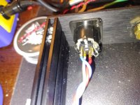
What I don't see is whether the other end from power supply, with the male XLR jack (on end of umbilical) there is also a pin#1 and small tab. I don't see where it shows them shorted. Also on that end of umbilical, should the shield also be shorted to that same tab that pin #1 is shorted to.
What I don't see is whether the other end from power supply, with the male XLR jack (on end of umbilical) there is also a pin#1 and small tab. I don't see where it shows them shorted. Also on that end of umbilical, should the shield also be shorted to that same tab that pin #1 is shorted to.
Attachments
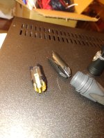
Speaking of the 4 pin XLR plug on end of umbilical that tab is small. I guess best to solder twisted shield in pin #1, then take wire from there to the tab.
I will start with this arrangement and see if it is quiet or not, and go from there.
Thanks,
Russellc
I will start with this arrangement and see if it is quiet or not, and go from there.
Thanks,
Russellc
Right. Got you.
One expects that the housings of the XLR jack (panel) and plug (cable end) will help with the task of shielding and therefore be connected to ground somehow, somewhere. Connecting the cable braid/shield as you describe should do that.
One might also assume (hope) that when plug is mated to jack that an electrical connection is made between the two. Connecting pins 1 to tabs in each might change that from a hope to a certainty.
- Home
- Amplifiers
- Pass Labs
- Pearl 3 Burning Amp 2023