I agree wrt the OPA891 which is recommended (by TI) as a replacement for the LME's -- it's really an outlier. I don't have a sample to test, and that's what dumped out of the simulation.Interesting, I have taken the liberty of expanding your table with voltage and current noise @1000Hz and sorting by the integrated-noise value.
I do suspect that the model for OPA891 is not weighting current noise properly.
As I said in the post, one leg of the compensation caps is lifted off the PCB to give the true broad-band performance.
It's also important to remember that our ears are most sensitive to noise around 6.3kHz.
The OPA891 is not available anywhere!!! There's a dual of the OPA891 -- OPA2891 but it isn't available either.
Last edited:
Hello All,
Went looking around, things seem to hide from you after you move.
Tested the P3 again today with different test leads, too short to get more than a couple of feet away from the bench with all the AC connected devices, There is less AC power Line Harmonics leaking into the P3 input today. I ordered from Mouser longer and I hope better Pomona test leads.
I have looked around at test reviews of other Vinyl pre-amps with the state of the BNC test leads on the bench today’s’ P3 test plots are as good as or better than I was able to observe on line.
At 5mV input the Gain at 1K was 50.4db. The output fell at 1.656 VRMS (more than you would ever use, “turn it down”).
The THD+N was 0.005%
Thanks DT
See the test plots below:

How does this vintage phono preamp compare?
There are a lot of measurements but but don't know if you can compare them 1 to 1.
The reviewer seems very happy with its performance.
https://www.audiosciencereview.com/...mono-preamplifier-by-2r-vintage-review.32203/
It was an expensive amp when it was at the market 30-35 years ago or so.
I can say that I am very happy with my P3. No audible hum if I turn volumen up all the way to max. I have 49 dB (MM setting) + 12 dB (IronPre) gain (94 dB speakers). I had a HiFi-friend to a listening session and he was impressed too. It was the most silent setup he had experienced. Then I can conclude that my grounding scheme works 🙂
Edit: forget about the vintage preamp measurements. Seems he does not measure the phono part of the amp.
Last edited:
Ha ha...........Edit: forget about the vintage preamp measurements. Seems he does not measure the phono part of the amp.
Maybe because this pre never had a riaa/phono-pre built in to begin with 😉
Hence, the name of the unit being "Line Stage".
Gryphon Line Stage
Ok, yes but then it got it afterwards or there were two models 🙂

At least there are Phono inputs. Same concept as P3 with dual mono possibility and external PSU. There are also power inputs the call Power MC......special power for Moving Coil?
But back to Pearl3 topic.....
At least there are Phono inputs. Same concept as P3 with dual mono possibility and external PSU. There are also power inputs the call Power MC......special power for Moving Coil?
But back to Pearl3 topic.....
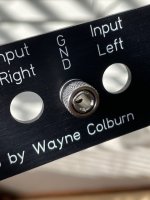
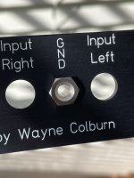
GND Post Options
I found a couple of nice grounding post / jack alternatives for my Pearl 3, and figured others might be interested:
• Cinch 111-2223-001 - uninsulated binding post with knurled thumb nut, nickel
Very reminiscent if not identical to the ground posts found on 70's - 80's vintage Tektronix test equipment. TM500, 7k series scopes, etc. In fact, noticing the ground lug on one of my Tek scopes shortly after my chassis kit arrived is precisely what inspired me to go searching for a similar grounding terminal, and I was delighted to find these. Knurled thumb nut is captive. This one did not come with a ring terminal; just the inside nut is included.
• Cinch 108-0740-102 - uninsulated low profile banana jack, nickel
These have a really nice low-profile look, which might suit those who know they only need a banana receptacle for their grounding wire. This one comes with a solder-tag ring terminal.
Both are available from Mouser, and both require drilling the rear panel hole to ø 0.25 in.
I'll be going with the knurled thumb nut version myself. 🙂
Attachments
Hello All,
Still sorting the P3 on my my bench. Your mileage may vary.
I have been over at the ap.com site looking into measuring the results of the P3 RIAA pre-amplifier fabricated hear on my bench.
Using the Audio Precession Inverse RIAA Equalization Curve the a vinyl pre amp would produce a horizontal straight line on the FR Plot. The plot pretty much shows + / - 0.1dB of a flat line on the plot.
The Low Frequency ~0.3dB roll off is the the result of the IES amendment built into the design. I think.
Thanks DT
Looks good on the frequency response and noise DT. Love those RN60 resistors.
The jfets are closely matched 2SK170’s with an Idss of 7.4ma. The current measured across R10 is a total current of 12ma.
I think you meant R1?
I am also going to use 2SK170's from my stash, I have a closely matched octet at 6.3mA Idss which I've been saving for a new phono.
But looking at the data sheet curves I estimate I should get about 12 mA through Q5 C-E & R1 ... now, I've been trying to figure out how that doesn't just saturate the collector of Q5, because it's base should be sitting at about 7.1V, and at 12 mA, R1 should be dropping 9V. Have I mucked up my math somewhere, or does R1 value need a little adjustment based on the JFET you stuff? Wayne mentioned the K170's should just drop right in.
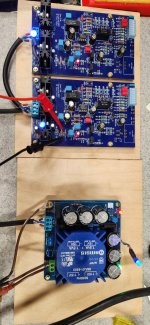
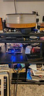
It's alive and sounds great! Just ordered the case. Sitting out in the open on a piece of wood it is spooky quiet with nothing playing.
Measuring -14.9 and +15.2 on both channels. With R27 at 680R one channel is 3.90mA and the other is 4.35mA. That is the extent of my testing.
Not much of a reviewer but this thing is a keeper! I think I now understand what people mean by a blacker background. Sound stage is really good and it is easier to notice all the various details in the music.
Thanks to everyone that made this possible, and for all of the help and inspiration provided by this forum!
Attachments
I think you meant R1?
Good eye, you have to keep an eye on me. It was R8 I did the current calculations with.
E = IR, voltage drop across R8 / 10 Ohms equals total current through R8 or 12ma +/- a red curly hair.
OK, I didn't account for Q5 base current pulling the R2 / R3 bias network to roughly 0.6V lower. I'm still not sure that leaves enough voltage on Q5 collector without reducing R1 though...
With my pencil, paper and HP calculator it looks like with this circuit there is a voltage divider thing going on. From the reports of other members here on diyAudio it looks like we get about 41% of jfet Idss measured across R8. For your matched 2SK170 sets of 4 jfets that is 6.3ma * 4 * 0.41 gets ~= 10.33ma total current through R8.
This is right in the center of good, this is more Idss current than the GR 2SK209's that most people are using. You likely do not need to change anything.
Thanks DT
Last edited:
Looks good on the frequency response and noise DT. Love those RN60 resistors.
Hello,
It is raining buckets here in NorCal.
While it is wet out I am having a good time trying things and working with your P3 project and PCB.
Thanks for sharing your P3 design with us.
DT
The OPA891 is available at the TI store. Some are arriving today. The OPA2891 not yet.The OPA891 is not available anywhere!!! There's a dual of the OPA891 -- OPA2891 but it isn't available either.
@bentconvert Fantastic! Looking great, will be excited to see what you do for a chassis!
And yes, it really does sound amazing, doesn’t it?
😎
And yes, it really does sound amazing, doesn’t it?
😎
Hi Dualtriode,
would you be so kind to make and show a THD vs. V Input of the P3? At 1k Hz would be fine.
Thx.
would you be so kind to make and show a THD vs. V Input of the P3? At 1k Hz would be fine.
Thx.
Speaking of op-amp noise...
I was looking over the design to see if I could spot any areas to improve... Wayne has done a thorough job on this, I see very little fat left to trim. But if we're splitting hairs with quieter op-amps, then we might as well expand the scope of our search.
I did some more math (uh oh!), and R10 at 22 kΩ contributes about as much thermal noise as the input JFETs (accounting for +30 dB gain at the collector of Q5). 22 kΩ gives 19 nV/rt(Hz) on it's own, just a hair less than the JFET's 0.64 nV, +30dB => 20 nV/rt(Hz) at C1, the input into the U1A gain stage. This is quite a bit more than the en of most of these op-amps. Mind you, R10 (along with U1A) is within the feedback loop back to the input JFET sources, so its noise contribution will be reduced by the NFB ratio. Nevertheless, lowering the value of R10 might be of marginal benefit if the goal is to squeeze out every last drop of noise performance.
Lowering R10 to 5 kΩ cuts its noise contribution in half, and also reduces the op-amp's input current noise contribution (perhaps of benefit to some of the bipolar type op-amps). If we did nothing else, the pole contributed by C1 would move up but then the higher gain of U1A (and thus greater NFB around it) would push the pole frequency back down to the original design point. But, higher U1A gain may run some stability risk, depending on the particular op-amp and how much gain / phase margin it has available. So this should not be undertaken without some measurements to verify stability!
Panasonic makes a 2.2µF cap that fits the C1 footprint (ECW-FE2W225J). Lowering R11 to 500 kΩ in combination with the 2.2 µF cap brings U1A gain to only 6dB more than originally designed, and retains the closed-loop pole location. The added gain will further help reduce the noise contribution of Q5 / R1 / R10 / U1A but this is added NFB around the JFET input stage, so it's going to have an effect on the distortion profile as well. The other side effect here is that R10 is also loading the cascode collector in parallel with R1, so we lose a bit of gain on the JFET input stage. About -1.2dB at 5 kΩ. In terms of noise, I would posit that 5 kΩ is already down into diminishing returns as far as noise reduction, so going even lower is probably not a good trade-off since the JFET front end will start losing appreciable gain.
Long story short, there's little reason to alter the original design values, but if optimizing noise that last whisker is a priority, then adjusting R10 might be worthy of consideration. I've not done any stability or distortion measurements with this mod yet, and whether it's worth the trade-offs is certainly debatable. Just throwing this out there for the more adventurous types to ponder...
Last edited:
If you suspect resistor "R999" on the Pearl 3 contributes to thermal noise, you can try a quick experiment at home.
Don't forget that Johnson-Nyquist thermal noise is proportional to the square root of resistance (thus "Lowering R10 to 5 kΩ cuts its noise contribution in half" is incorrect), and likewise thermal noise is proportional to the square root of absolute ("Kelvin") temperature.
- Attach a turntable+cartridge to Pearl 3 but don't play a record. Just let the arm sit on its rest.
- Turn up the volume to max so you can hear all of the noise in your speakers
- Blast resistor R999 with electronics freeze spray for 20 seconds, and lower its temperature by 100C
- Did the noise from the speakers decrease? If so then R999 is a culprit. If not then forget R999.
Don't forget that Johnson-Nyquist thermal noise is proportional to the square root of resistance (thus "Lowering R10 to 5 kΩ cuts its noise contribution in half" is incorrect), and likewise thermal noise is proportional to the square root of absolute ("Kelvin") temperature.
Last edited:
- Home
- Amplifiers
- Pass Labs
- Pearl 3 Burning Amp 2023