is the correct transistor coupled to the heatsink?MJL21193 said:I'm not feeling the love for this new Vbe arrangement. It drifts like crazy and I can't seem to do anything to fix it.
Or
should both transistors be thermally coupled?
I hate your 337 solution for VAS CCS.
A red LED + 120V transistor + resistor is a tried and tested method that works, or use the existing red LED to save on components.
MJL21193, maybe a different approach is needed here, if you give me your email Ill send you a pdf inform.
Hi,BV said:
M337 datasheet...
Yes, I knew the voltage limit on the regulator, I just mainly wanted to know if it was a viable option for a CCS and if I had it set up properly.
AndrewT said:is the correct transistor coupled to the heatsink?
Or
should both transistors be thermally coupled?
I hate your 337 solution for VAS CCS.
A red LED + 120V transistor + resistor is a tried and tested method that works, or use the existing red LED to save on components.
Don't worry Andrew, I'm not forsaking the bootstrap for that. 😉
The regulator was me playing around, but it seems to perform very well in that role (given voltage constraints 🙂 )
As for the bias, I'm going by what Glen said, that the second T could be board mounted. It's too late anyway - I've decided to go back to the single T, just adding the collector resistor. I said from the start that the voltage fluctuation was not an issue (for me) and that it's attempting to fix something that is not broken.
homemodder said:MJL21193, maybe a different approach is needed here, if you give me your email Ill send you a pdf inform.
Hi, I'll send it to you. I'm always interested in new approaches.
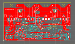
I'm working on the board layout AGAIN(!!!!!!). This time for the last time as far as this amp is concerned (what? never say never?).
I need to be getting six of these made, plus the chassis to put these into service. I think that we have pushed the design to a new high and it betters the original by a wide margin.
Sound quality, there doesn't appear to be much of a difference (to my ears). Definite improvements in stability, clipping performance, economy, distortion(?), power output and overall design enhancement.
Is there room for more improvement? Some would say no, without changing the basic topology. But then it becomes something else.
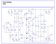
Anyway, I'm going to go with it and I'll post a final schematic shortly. It has been very fun and educational, as usual.
MJL21193 said:I'm not feeling the love for this new Vbe arrangement. It drifts like crazy and I can't seem to do anything to fix it.
Was the adjustment pot a new one or did you remove it from another piece of gear?
Also, it's a good idea to put a resistor in series with the pot to limit the adjustment range of the bias circuit. This will allow finer adjustment.
New pot (fresh crop 😀 ).
It's ok, I'm not going to try to make that Vbe multiplier work as the one I had in the first place does a great job.
I want to further the development of this amp design but I need to take what we have right now and use it. When too many changes happen, the identity is lost.
So, the upcoming schematic will be the final for the Patchwork. Anything else that comes after will be under a different name.
There are things I'd like to try and areas I'd like to explore but all in good time. It's all part of my ongoing "education"
I took a break from theory today to get my hands dirty 🙂
I finished the other heatsink and decided that I would bolt on an angle to provide the mounting surface for the amp modules. This also straightens out the heatsinks, which had a slight bow.
Here's the first. The angle is 3/16 aluminum, 2" wide on the heatsink and 3.5" sticking out. Amp module laid in place to give perspective.

Both of the mirror image heatsinks laid out with one of the power supplies and the 750VA transformer. I made up that block of clear straight grained fir for the front panel. I haven't made up my mind on how I want it to look, but I thought I go with wood for a change.

Of course lots left to do but I'm making progress.
I finished the other heatsink and decided that I would bolt on an angle to provide the mounting surface for the amp modules. This also straightens out the heatsinks, which had a slight bow.
Here's the first. The angle is 3/16 aluminum, 2" wide on the heatsink and 3.5" sticking out. Amp module laid in place to give perspective.
Both of the mirror image heatsinks laid out with one of the power supplies and the 750VA transformer. I made up that block of clear straight grained fir for the front panel. I haven't made up my mind on how I want it to look, but I thought I go with wood for a change.
Of course lots left to do but I'm making progress.
MJL21193 said:
Sometimes you need to improvise. 🙂
I'm not feeling the love for this new Vbe arrangement. It drifts like crazy and I can't seem to do anything to fix it.
There is something funny going on here. Are you using one of those recycled TO-92's for the PNP trannie?
I'd try replacing both the NPN and the PNP before giving up.
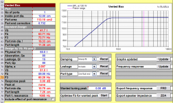
BTW (OT), since you are the resident Unibox expert, what bass reflex results do you get for the 5320 driver here:
http://www.phlaudio.com/datasheets/38_pdf/5320_5370.pdf
PHL says use Vb=65L and tune to 46Hz. I tried, but I keep getting BS figures for the port length.
Cheers,
Glen
Nice progress 🙂
re the two-transistor VBE, I remember reading a few things about this, and t is the FIRST transistor that should be thermally coupled, not the second. I don't think it's worth pursuing these days though... a single TO-126 device mounted to the heatsink works well.
re the two-transistor VBE, I remember reading a few things about this, and t is the FIRST transistor that should be thermally coupled, not the second. I don't think it's worth pursuing these days though... a single TO-126 device mounted to the heatsink works well.
G.Kleinschmidt said:
There is something funny going on here. Are you using one of those recycled TO-92's for the PNP trannie?
I'd try replacing both the NPN and the PNP before giving up.
No recycled parts, but my spider sense was tingling about something funny going on, anyway...
Too late. I've given up on that and have been working on the board layout with the old (reliable) Vbe.
Next time.
G.Kleinschmidt said:
BTW (OT), since you are the resident Unibox expert, what bass reflex results do you get for the 5320 driver here:
http://www.phlaudio.com/datasheets/38_pdf/5320_5370.pdf
PHL says use Vb=65L and tune to 46Hz. I tried, but I keep getting BS figures for the port length.
Expert, eh?
That driver CAN be in a 65L box tuned to 46Hz with a port dia. 10.4cm x len. 15.6cm but it will give better response in a 60L tuned to 59Hz.
What are you planning for that one?
Attachments
jaycee said:Nice progress 🙂
re the two-transistor VBE, I remember reading a few things about this, and t is the FIRST transistor that should be thermally coupled, not the second. I don't think it's worth pursuing these days though... a single TO-126 device mounted to the heatsink works well.
Thanks jaycee,
What can I say - I agree 🙂
Still working on the layout. I had a lot done, forgetting to save (in a trance) and lost all of the work when the program "encountered a problem" and shut down. Nice.
Attachments
AndyC
Ive been researching some suitible diodes for use as clamps and found a excellent range of japanese diodes, is there any real advantage that can be measured or heard with a faster recovery part. What relevance is it of say using a 100 or 150 ns part. The very low capacitance is of great importance but speed??? There are some japanese parts that have 1.5 pF, 1amp and 200v reverse capability.
Ive been researching some suitible diodes for use as clamps and found a excellent range of japanese diodes, is there any real advantage that can be measured or heard with a faster recovery part. What relevance is it of say using a 100 or 150 ns part. The very low capacitance is of great importance but speed??? There are some japanese parts that have 1.5 pF, 1amp and 200v reverse capability.
MJL21193 said:
No recycled parts, but my spider sense was tingling about something funny going on, anyway...
Too late. I've given up on that and have been working on the board layout with the old (reliable) Vbe.
Next time.
Well that’s your prerogative.
MJL21193 said:What are you planning for that one?
Stuff
Cheers,
Glen
homemodder said:AndyC
Ive been researching some suitible diodes for use as clamps and found a excellent range of japanese diodes, is there any real advantage that can be measured or heard with a faster recovery part. What relevance is it of say using a 100 or 150 ns part. The very low capacitance is of great importance but speed??? There are some japanese parts that have 1.5 pF, 1amp and 200v reverse capability.
Looking at the Fairchild BAV21 data sheet, the reverse recovery time is 50 ns max, and typical capacitance varies from 1.15 pF at 0V to 0.9 pF at 15 V reverse voltage. I'm not sure about the availability of these outside the U.S. though.
Reverse recovery time specifies how fast the device can be turned off after it's turned on. So having a faster reverse recovery time would, all other things being equal, result in faster recovery from clipping. But there's all sorts of other things that affect clipping recovery, such as the dynamic nonlinear behavior of the feedback loop, which may dominate. Also not all reverse recovery times are created equal. They spec a forward current at turn-on, then a peak reverse current (due to stored charge) during the turn-off portion, then a final reverse current which is typically 1/10 of the peak reverse current. So for the same diode, many reverse recovery times could be defined depending on the current values chosen. A 1A forward current spec is overkill, and probably implies a device that's slower than a lower current device (because of larger junction area).
If the amp does not clip, the reverse recovery time trr of the diode is not relevant. What trr really boils down to is the capacitive portion of the diode impedance in the forward biased state.
andy_c said:
Looking at the Fairchild BAV21 data sheet, the reverse recovery time is 50 ns max, and typical capacitance varies from 1.15 pF at 0V to 0.9 pF at 15 V reverse voltage. I'm not sure about the availability of these outside the U.S. though.
Hi Andy,
I want to order some different drivers from Digikey (2SA1837 / 2SC4793) to use instead of the 2SA1011/2344 mainly because of the insulated package. That's that, but I want to get the clamping diodes there too. Unfortunately, they only have surface mount, but I thought I'd solder a couple leads on and use it through hole.
Anyway, while searching I found the BAV103. This is a slightly bigger package so it would be a bit easier to Jerry up.
These are very similar, no?
Those look good too, but why not solder them on surface mount? I believe it will be much harder to try to solder on legs as they'll fall off when you heat it. Soldering "big" surface mount parts isn't that hard. 🙂
megajocke said:Those look good too, but why not solder them on surface mount? I believe it will be much harder to try to solder on legs as they'll fall off when you heat it. Soldering "big" surface mount parts isn't that hard. 🙂
Hi Mega,
That's good news.
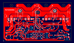
I think I can manage to get it soldered and besides, I went through 6 board revisions for this amp and I can't do another. I should have laid out these for surface mount in the first place. No problem on D2, but D1 has a wide power trace running through it.
I'm seriously thinking of going more that way for future projects. I can make a pretty good board with very fine traces so that wouldn't be an obstacle.
I've put through the order to Digikey - should be here tomorrow.
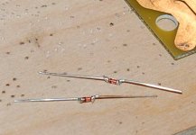
Some new drivers for these six:2SA1837 and 2SC4793.
Mica TO-3 isolation pads to cut down to TO-264 size as they don't have mica pads for these (????)
Some new Vishay/Dale .3R ballast resistors and of course the BAV103 MINIMELF package diodes.
Started on six new PC boards with 2 finished already. It gets boring after a while. 🙂
This leaves me with two fully assembled prototypes that I guess I'll strip. Seems a waste to do this, but it's the only way I can do the testing. I've done the breadboard thing and catapulted that into the forest behind my house.
I cringe every time I see perf board...

- Status
- Not open for further replies.
- Home
- Amplifiers
- Solid State
- Patchwork Reloaded: Circuit Optimization and Board Layout.