Now that's really hard to improve on.
I've got those green caps, would be really glad if you could e-mail me the schematic for biasing the digital cable. BTW i have just finished building my new DAC. I'm using CS8420 with 0.01u coupling caps. I found out that bigger MIT caps sound better comparing to WIMAs. Is there any drawback for using physically big caps in that location. I also tried coupling transformer from Digi-Key but it didn't sound good. On the other hand using transformer in the transport's output improved the sound.
Peter
planet10 said:
I haven't gone that far, but Al or Cu or brass generally sound better than steel.
dave
agreed but Al or Cu etc still provide a degree of shielding
AudioFreak said:
agreed but Al or Cu etc still provide a degree of shielding
Cu provides ALOT of shielding
dave
planet10 said:
Cu provides ALOT of shielding
dave
Yep, sure does .... point i was trying to make is that unsheilded is not better than non ferrous sheilding 🙂
What value do you take for the input filter ?
Did I get the connection right : say, 1k Holco, 100p to ground, than 10k Caddock to the wiper ?
Klaus
Did I get the connection right : say, 1k Holco, 100p to ground, than 10k Caddock to the wiper ?
Klaus
Passive preamps are very very attracting, but do have a lot of problems. They depend on a lot of other things to sound good. Source output voltage and impendance, input and output cable impendance and so on.
I have tried a lot of different passive preamps because they are cheap even with good parts. They lack dynamics, but I have an idea from a friend how to equaize the problems from cables and sources.
If you are intested look here.
http://mitglied.lycos.de/Promitheus/equalized_passive_preamp.htm
I have tried a lot of different passive preamps because they are cheap even with good parts. They lack dynamics, but I have an idea from a friend how to equaize the problems from cables and sources.
If you are intested look here.
http://mitglied.lycos.de/Promitheus/equalized_passive_preamp.htm
Passives and the cable interface
promitheus,
Your post raises several interesting points.
Use short and low capacitance cable to control high frequency roll off. Yes absolutely.
The bandwidth of the cable interface beween the source and passive preamp input is controlled by the output inpedence of the source (usually in the 10 to 1000 ohm range.)
Active circuits can have a little better dynamics and I will post an buffered passive circuit later. This is also very dependendent on the cable used.
The article was interesting on first glance but There are some things in it that I question as accurate in the modeling part that are too involved to go into here. The circuit would have to be optimized for specific cable types and even lengths. I good buffer circuit would be a better solution for most people. I see that he used transmission line models for the cables which are really only useful at RF frequencies. A lumped capacitance model would be fine at audio frequencies.
It is amazing that the wire designers never seem to mention how different this interface is between diffent brands of equipment. I do see a trend to lower capacitance designs though which should help matters. The performance at RF frequencies is a whole other subject and can influence the sound due to all the RFI in the enviroment.
You have certainly lit a fire under us mortals to investgate this cable interface in more detail. It should generate plenty of smoke and flames and ultimately shed plenty of light on the subject. We will not punish you for it but rather thank you for igniting our interest in the subject.
H.H.
I found this article once in a magazine and was very interested.
It doesn´t work with all cables and circuits, like plug and play. As you said it must be optimised. You have to tune it like you you calibrate an osciliscope probe with its internal generator so you make the pulses square.
I think the original circuit has trimming pots.
It doesn´t work with all cables and circuits, like plug and play. As you said it must be optimised. You have to tune it like you you calibrate an osciliscope probe with its internal generator so you make the pulses square.
I think the original circuit has trimming pots.
Hey Hairy Holler:
Maybe you found someone other than me that knows enough to give you a hard time!
Keep up the good work, Promitheus.
Jocko
Maybe you found someone other than me that knows enough to give you a hard time!
Keep up the good work, Promitheus.
Jocko
Playing with fire
Jocko and Promitheus,
Feel free to keep me on my toes... I am big enough to get flamed if you feel I am blowing smoke. Besides, if you can't stand the heat stay away from the solding iron......
H.H.
Jocko and Promitheus,
Feel free to keep me on my toes... I am big enough to get flamed if you feel I am blowing smoke. Besides, if you can't stand the heat stay away from the solding iron......
H.H.
Although I was VERY sceptic about passive controllers with high impedances (because of bad experiences in the past) I am changing my point of view now. I must admit, although I knew about the shunt principle, I never actually tried it in practice.
A few experiments with a stereo pot lying in my spares box (ha! spares! a lot of crap...) gave very interesting new results. Assuming the right driving impedance and cable consist I am beginning to get a nwe picture. But - stil sceptic - I will have to test it much more throughly.
Again, HH, how are your input filters constructed ?
Klaus
Passive passions
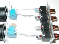
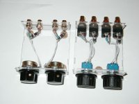
For input filters I like to use a series resistance close to the characteristic impedance of the cable from the source to passive box. The capacitor from this series resistor to ground should be chosen to give a corner frequency of about 200kHz. The corner frequency is set by the output resistance of the source and the cable capacitance plus this capacitor. A nominal value for the less mathematical might be 75 ohms and 200pF. The RC filter can be mounted on the input jack. This is a good subject for a simple Spice model. I have just constructed a unit with these values and it sounds wunderbar. This new passive uses 50K linear taper Bourns conductive plastic pots with a 9K one watt Corning glass substrate resistor across the output jack. This is the law faking configuration mentioned on the ESP website. I used OFC copper, gold plated jacks from Sound Connections and 30 guage 99.99%silver wire. Absolutely amazing sounding and it cost under $50!
H.H.
Passive update
I liked the sound of the passive with the bourns pots, input filter and silver wire so much that I updated the Radio Shack passive with same 9K Corning resistors, 63 ohm Cornings/200pF polystyrene cap input filter, and 30 gauge silver wire. Still under $30 for Radio Shack vesion with smart surpluss store shopping. I used teflon sleeving and lightly twisted the wires for more noise immunity.
H.H.
Attachments
solder sounds
Hello Harry and All,
I agree with and I'm interested in your comments of solders sounding different.
Are the solders you refer to Multicore 96S (96%tin, 4% silver), and LMP (60% lead, 38%tin , 2% silver) ?
Have you tried Savbit (60%lead, 38%tin, 2% copper) ?
Can you express to us the differences you find ?
Also agree with removing teflon sleeving - I don't really like the sound of teflon in my experience - funny shitty false highs sound when on wires I reckon.
Also have had amplifier running full power on my bench and refitted top cover ( aluminium ) and the sound changed ?
What the ......
I removed it and the sound reverted.
Next I tried steel cover from another amp and different sound.
Then I tried wooden cover from another amp and another sound.
What the, What the ......
I found the wooden cover to impart a nicer sound.
Old timber covered amps have a particular flavour (Old Pioneers and Akais etc), not heard anymore.
I say aluminium (cabinets and heatsinks) sounds like an empty Coke can being kicked down the road - not friendly to my ears !
My favorite amp has copper heatsinks !
In further experiments, I also found old well annealed copper cover and earth busses to give nice sound.
Regards, Eric.
PS - Kostas Metaxus made comments regarding stainless steel enclosures ( non magnetic type of SS I think ) but I never really liked the sound of these amps and cdp.
Buffer
Check out the JFet follower circuits in the part 2 article on jfets at
http://www.borbelyaudio.com/ I'm working on a couple of variations on the fet follower and will post after some listening experience. I have had great results with K170s jfets biased with jfet or mosfet current sources.
H.H.
Check out the JFet follower circuits in the part 2 article on jfets at
http://www.borbelyaudio.com/ I'm working on a couple of variations on the fet follower and will post after some listening experience. I have had great results with K170s jfets biased with jfet or mosfet current sources.
H.H.
unity gain buffers
Some ideas for you "glow in dark" types.
http://www.tubecad.com/october99/
http://www.tubecad.com/articles_2002/Power_Buffers/page3.html
H.H.
Some ideas for you "glow in dark" types.
http://www.tubecad.com/october99/
http://www.tubecad.com/articles_2002/Power_Buffers/page3.html
H.H.
FYI - HiFiWorld had a construction article in the early 90's, complete with trimmer cap for a passive pre, for matching characteristics to the cables (who's charateristics they tabularly listed). Periodically I archive my mags with a friend with more storge space, and I'll see if I can dig the article up, unless someone else can find and post the schematic...
- Status
- Not open for further replies.
- Home
- General Interest
- Everything Else
- Passive Preamp