Nelson, did you have a chance to look at the measurements of the HPD drivers made by fabrice63?
No. I was unable to access from the link.
Attachments

Nice job man ;-)
regarding the db conversion , I was asking myself the same question, but what db are we looking after , dbv or dvu , both ?
.
regarding the db conversion , I was asking myself the same question, but what db are we looking after , dbv or dvu , both ?
.
Last edited:
Have a look here ...
dB chart voltage power table conversion sound pressure sound intensity decibel voltage level levels ratio dbu dBA dBm absolute relative acoustic measurement volts watts and pascals database - sengpielaudio Sengpiel Berlin
Or, if the conversion you are looking for is not on that page, it's probably somewhere here:
Audio calculations in English acoustics calculator convert audio formulas sound dB audio system microphone electro engineering electronics formula sound recording studio useful stuff free audio calculator recording studio acoustic audio engineering s
🙂
Best regards, Claas
There are dB calculators on the internet. E.g.
Decibels to Voltage Gain and Loss convert calculation conversion amplification amplifier electronics - sengpielaudio Sengpiel Berlin
dB is 20 * log(Vout/Vin) ...if it is voltage amplification.
I guess you should just set Vin = 1 and then use your values as 20 x log(V) for all the voltage values.
Decibels to Voltage Gain and Loss convert calculation conversion amplification amplifier electronics - sengpielaudio Sengpiel Berlin
dB is 20 * log(Vout/Vin) ...if it is voltage amplification.
I guess you should just set Vin = 1 and then use your values as 20 x log(V) for all the voltage values.

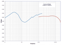
dB is 20 * log(Vout/Vin)
Is there a scaling factor missing? Normakized to the 1st measurement at 10Hz.
dave
Attachments
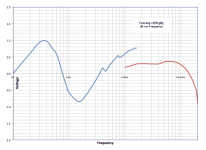
Here is the result, bigish dip in the 3500 to 500hz area.
This measurement was inside so bass is a bit over the place.
Thanks
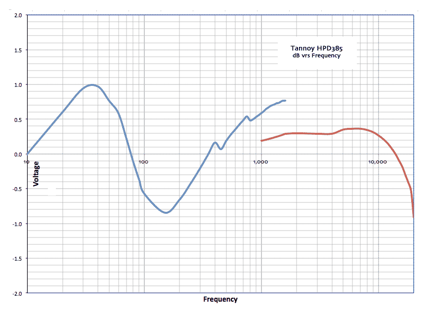
The ripple of the low frequency driver seems notable. It reminds me of the ripple that occurs with an unstuffed transmission line for the octaves immediately above the 1/4 wave length tuning frequency. I have never seen a room do this to a speaker. I have seen this when you attach a driver to a long PVC pipe.
Yea the bass is a bit wobbly but those are room nodes as the measurements were taken inside. The dip that concerns me is the top of the mid drivers range which when summed makes the dip from 3500 to 5000hz. (Not 3500-500 as first mentioned.)
Trouble the natural roll off of these drivers is virtually identical to the cross over, the crossover really only appears to provide protection.
Trouble the natural roll off of these drivers is virtually identical to the cross over, the crossover really only appears to provide protection.
Is there a scaling factor missing? Normakized to the 1st measurement at 10Hz.
dave
As far as I know dB is just a way (logarithmically) to show the relation between an input and an output. Then it has been defined the way it is so 6 or 3 dB is x2 depending on if it is voltage or watt. Then the curve is compressed compared to just showing the linear relation.
Here is the result, bigish dip in the 3500 to 500hz area.
This measurement was inside so bass is a bit over the place.
That's a good looking result, the response is flat where the drivers
meet at around -6dB. If you were to invert the phase of one driver
you should see a good null at that point.
I tried inverting one of the drivers but that just made things worse... I was thinking that your new xover might be able to provide compensation for the early drop off on the mid range as shown in the individual plots.
Or...... should I not worry about this dip? Just that I thought a fair bit of music detail would be contained in this 3500-5000hz range.
Or...... should I not worry about this dip? Just that I thought a fair bit of music detail would be contained in this 3500-5000hz range.
You will need a more advanced crossover than the ones discussed here in order to rule out the irregularities above 2kHz.
There are several pages describing extensive upgrades to the HPD 385’s crossover
tannoy hpd 385 crossover upgrade - Google Search
But I think that much of the aberrations on these puppies above 2000 - 2500Hz would be require more correction along the lines of multiple parametric EQ to arrive close to “flat”response
Measured FR curves from Tannoy, and a couple of independent sources:
tannoy hpd 385 frequency response measurements - Google Search
Not a fan of the couple of factory builds that I’ve heard - Westminsters and Ardens, plus a custom built pair of 12” in “small” stand mounted, and 15” in fridge sized Churchill knock-offs. To each his own
- Home
- Amplifiers
- Pass Labs
- Pass Labs B4 crossover questions