You could use a single cd4017b decade counter set up so each press of a single switch selects the next input. Also a debounce circuit using a schmitt trigger would work well.
why not using Hall for input switching?
if Hall is too expensive and rare , Arduino is next option

if Hall is too expensive and rare , Arduino is next option
I found a website that shows a guy using a decade counter to turn on led's. The decade counter may already have a schmitt trigger inside on it's input. Switch Bounce and How to Deal with It
All this talk of the switch circuit...what about the amp circuit!
I am perplexed at why there is a servo on headphone out but a cap on line out.
A cap on the headphone out would have to be giant, so I understand the need for servo.
But line out sounds better with a cap? Only Jam knows for sure...
I am perplexed at why there is a servo on headphone out but a cap on line out.
A cap on the headphone out would have to be giant, so I understand the need for servo.
But line out sounds better with a cap? Only Jam knows for sure...
Is Q4 installed correctly?
Nice catch! It's backwards all right....
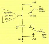
I prefer to short the headphones straight to ground when muting them (relay K4).
I also prefer to guarantee that both plates of the 10 microfarad PP capacitor are never floating. I want them biased to zero volts at all times, no matter which state the preamp-out relay is in (K3).
Something like the attached.
_
I also prefer to guarantee that both plates of the 10 microfarad PP capacitor are never floating. I want them biased to zero volts at all times, no matter which state the preamp-out relay is in (K3).
Something like the attached.
_
Attachments
IRF640 power MOSFETs in TO-220 packages, to drive relay coils??
When I started this project it was a little over my head. So when I needed a MOSFET and saw that Jam used a TO-220, I just went with a 610. (I suspect now that Jam used them because Pass Labs had a bunch of extras in a drawer -- but I don't really know.)
I was aware of the select-both-inputs anomaly. I don't plan on doing that, so I didn't design around it. Many of my other amps have the inscription on the back "User serviceability is entirely dependant on the skill of the user". Probably applies to the user usability too. 😉
way too complicated, what about a toggle switch ?
He he... this would be closer to my thinking.
Note that I also used a CMOS flip-flop so that I could remove the complexity of an additional (TTL-level) supply.
We drive relays with 4N20L TO-220. The L is logic level so you can count on them being turned on hard with a micro controller and they never break. And of course they are in stock.
We drive relays with 4N20L TO-220. The L is logic level so you can count on them being turned on hard with a micro controller and they never break. And of course they are in stock.
The IRF610 I'm using isn't logic-level, but I'm driving it with a CMOS flip-flop @ 12V, so the net result should be about the same. I'll take lucky. 🙂
I prefer to short the headphones straight to ground when muting them (relay K4).
I also prefer to guarantee that both plates of the 10 microfarad PP capacitor are never floating. I want them biased to zero volts at all times, no matter which state the preamp-out relay is in (K3).
Something like the attached.
_
Grounding only one side of the headphones doesn't worry me too much as there's nothing to pick up any stray induced voltages.
However, that's not the case with the line-out (if an attached amplifier is on), so it does seem like grounding the other side of the output cap would be a good idea.
Jeff, I find that what makes a BJT current mirror perform well, is to (a) include "emitter degeneration resistors" between the bipolars and the supply rail; (b) match those resistors to each other; (c) choose the resistor value so the voltage dropped across each emitter degeneration resistor is at least 250 mV
Why 250 mV? Because it is 10x bigger than (Ic / gm), namely the voltage dropped across the "intrinsic emitter resistance". It's also 50x bigger than the anticipated worst-case VBE mismatch, 5mV.
Try it out in circuit simulation. Just stick a 5mV voltage source in series with one of the two transistors' base. Voila, 5mV VBE offset. Now measure how well the current mirror achieves IOUT/IIN = 1.000
To match the resistors: buy five resistors in the required value. Measure their resistances and choose the two which are closest to each other. Discard the other three.
I sit and read in the background all the time and learn so much
To all of you thanks.

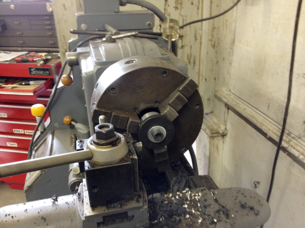
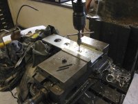
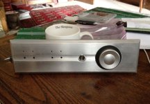
Turning the volume knob insert (I'm using black Richlite -- you get killed on setup charges when anodising one-offs):
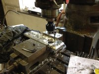
Boring a hole for the insert:
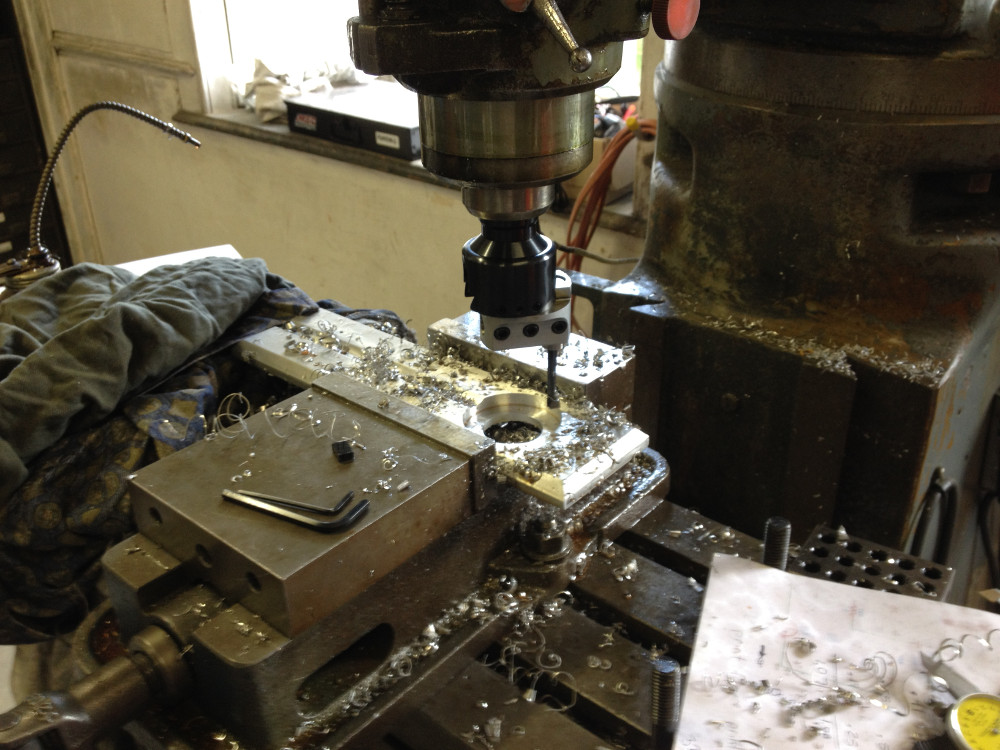
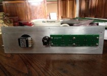
Tapping holes for the button PCB on the back of the faceplate:

Boring a hole for the insert:
Tapping holes for the button PCB on the back of the faceplate:
Attachments

- Home
- Amplifiers
- Pass Labs
- Pass HPA-1, what do we know?