Since we don’t know the exact schematic my advice would be:
Jfets matched
Current mirror bjt matched for hfe
Mosfet don’t need to be matched, but it will result in lower harmonics.
Servo only effects headphone out...looks like hpa1 has Silmics as line out output cap. Curious choice...why. It just use the servo for line out? Maybe caps are there for safety.
Jfets matched
Current mirror bjt matched for hfe
Mosfet don’t need to be matched, but it will result in lower harmonics.
Servo only effects headphone out...looks like hpa1 has Silmics as line out output cap. Curious choice...why. It just use the servo for line out? Maybe caps are there for safety.
I hope the coupling caps are just there for safety. At any rate, my clone (or perhaps just sibling) has the servo active for line output as well.
@Jam/@Wayne/@Nelson, how do feel about me posting my schematic?
Cheers,
Jeff.
@Jam/@Wayne/@Nelson, how do feel about me posting my schematic?
Cheers,
Jeff.
My guess is the coupling caps are there for sound...
For headphone use the coupling cap would have to be HUGE. Hence the servo.
Nobody here would use an electrolytic as a coupling cap given the choice...but Nelson/Jam/Wayne seem to do it all the time. They must know something we don't.
I use a conceptually similar circuit as preamp (by Juma):
LSK pre - BAF 2013
Sounds very good...and my listening impressions of it seem to line up with the reviews of the HPA-1 as a line amp. It does "sense of space" better than anything I have tried.

I think us Greedy Boyz are ecstatic but will immediately place you right on the very top of our wanted dead or alive list if it fails to deliver the expected "sense of space". 😀... how do feel about me posting my schematic?...
Last edited:
Well, that didn't work out as well as I had hoped.
I read up on current mirrors and it appears that the more important metric to match for them is Vbe. But within my Vbe measurement repeatability (+/-3mV) they were all pretty much identical (768+/-3mV).
hFE repeatability was better (+/-2), with the 20 samples (all on the same tape) ranging from 413 to 455.
So just match on hFE?
Jeff, I find that what makes a BJT current mirror perform well, is to (a) include "emitter degeneration resistors" between the bipolars and the supply rail; (b) match those resistors to each other; (c) choose the resistor value so the voltage dropped across each emitter degeneration resistor is at least 250 mV
Why 250 mV? Because it is 10x bigger than (Ic / gm), namely the voltage dropped across the "intrinsic emitter resistance". It's also 50x bigger than the anticipated worst-case VBE mismatch, 5mV.
Try it out in circuit simulation. Just stick a 5mV voltage source in series with one of the two transistors' base. Voila, 5mV VBE offset. Now measure how well the current mirror achieves IOUT/IIN = 1.000
To match the resistors: buy five resistors in the required value. Measure their resistances and choose the two which are closest to each other. Discard the other three.
Ha! Mark's post results in the light bulb going on. The HPA-1 employs non-1:1 current mirrors. That is, it's also using them for gain:
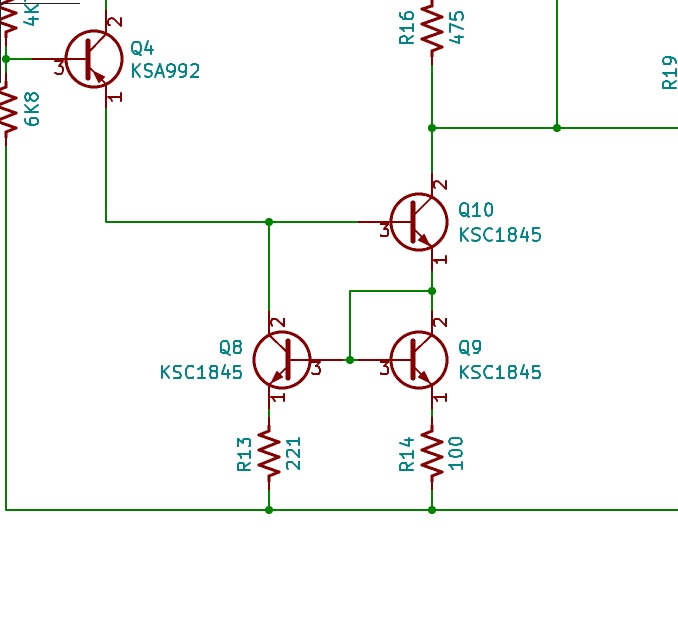
So what about matching top-to-bottom? No need, there's a trimmer for that.
And the light bulb goes on again. I nearly put my servo op-amps in without sockets. But it occurs to me now that I need to remove the op-amps in order to zero the offset to balance the current mirrors, etc.
Cheers,
Jeff.
So what about matching top-to-bottom? No need, there's a trimmer for that.
And the light bulb goes on again. I nearly put my servo op-amps in without sockets. But it occurs to me now that I need to remove the op-amps in order to zero the offset to balance the current mirrors, etc.
Cheers,
Jeff.
Attachments
Or just put a 2-pin header in series between the servo opamp output pin and the rest of the circuit. Install or remove a shorting block (link) on the header --> insert or remove the servo action. Works well and is easier & less error prone than pulling a DIP-8.
He he... but only works if you made the discovery before having the board made. 😉
Jeff,
can you pull off the leg ... one times bend I think it will do it and a litt little cut to the socket to remove the pin?!
can you pull off the leg ... one times bend I think it will do it and a litt little cut to the socket to remove the pin?!
Hi Jeff,
Thanks for contacting me.
Please post your schematic I am sure it would be of some interest to the community.
I will be glad to help with any questions that do not reveal any propriety information. I am no longer with Pass Labs and the design belongs to them.
I am working on a new balanced design but that is a few months away.
Jam
Thanks, Jam!
Disregard the part in my email where I ask again if I can post it -- I read these in the wrong order. 😉
Cheers,
Jeff.
Disregard the part in my email where I ask again if I can post it -- I read these in the wrong order. 😉
Cheers,
Jeff.
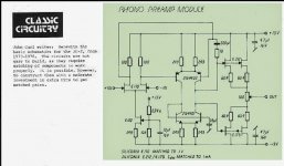
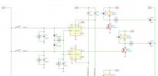
So here's my clone of the HPA-1.
BIG CAVEAT: This is based on Jam's descriptions earlier in the thread, hints from others, and some long hours studying not-quite-good-enough photos to discern connections and resistor values. Also, I'm an amateur in the analog domain, so while I now comprehend most of this circuit at a basic level, I certainly don't understand it well enough to know whether or not I got things wrong.
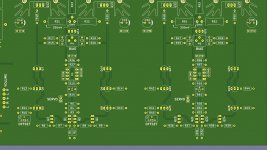
I'll post the Kicad files and/or Gerbers once I find out if it works or not.
Oh, and if you see issues with the design, please tell me! While I've already started building, I've got enough hours in the casework that I can do another board if necessary. 😉
Cheers,
Jeff.

BIG CAVEAT: This is based on Jam's descriptions earlier in the thread, hints from others, and some long hours studying not-quite-good-enough photos to discern connections and resistor values. Also, I'm an amateur in the analog domain, so while I now comprehend most of this circuit at a basic level, I certainly don't understand it well enough to know whether or not I got things wrong.
I'll post the Kicad files and/or Gerbers once I find out if it works or not.
Oh, and if you see issues with the design, please tell me! While I've already started building, I've got enough hours in the casework that I can do another board if necessary. 😉
Cheers,
Jeff.
Attachments
IRF640 power MOSFETs in TO-220 packages, to drive relay coils??
Also I am a little worried about the input select logic. A sick, sick person could press the SRC1 pushbutton and hold it down for 1 second. Then, while continuing to press SRC1, they could ALSO press SRC2 with another finger. Presto, both input select relays are energized, and the two sources are shorted together. Maybe not such a great outcome.
Probably a simple fix involving an AND gate and an inverter, could make this disappear.
_
Attachments
Member
Joined 2009
Paid Member
- Home
- Amplifiers
- Pass Labs
- Pass HPA-1, what do we know?