Cofee maker
Coffee warmer? Um-mm....it has set me thinking.....ya it is a brilliant idea. This is how you do it; don't directly wire the load in the circuit, instead fix a standard 15 amp wall outlet on the chassis. Thats it. Whenever you want to listen to some music with hot coffee, plug in the coffee maker or whatever into the socket, crank up the volume, and you shall have hot steaming coffee as a bonus while listening to your favorite music.
There are still alternatives, for example this 105W halogen light bulb. Take a look here:
Halogenglühlampe klar
I think, they are beautiful! 🙂 Manufactum says, that their phase out date is september 2016. 🙂
The water heater element idea is brilliant too! Think of an amp with included coffee/grog/glogg warmer! 😀 OK, liquids and electricity do not go together well...
Coffee warmer? Um-mm....it has set me thinking.....ya it is a brilliant idea. This is how you do it; don't directly wire the load in the circuit, instead fix a standard 15 amp wall outlet on the chassis. Thats it. Whenever you want to listen to some music with hot coffee, plug in the coffee maker or whatever into the socket, crank up the volume, and you shall have hot steaming coffee as a bonus while listening to your favorite music.

More serious: I think the only appropriate solution for the resistive load is the light bulbs. With them the Delite is not only a fine statement in simplicity but also in arts.
For my Delite project (planned in 2011) I'm thinking of a strange integrated / boom box Delite with open baffle fullrange speakers and loads of fretwork. What about the Jfet BOZ? Is it a good solution for driving the Delite? I think someone talked about it earlier in this thread.
For my Delite project (planned in 2011) I'm thinking of a strange integrated / boom box Delite with open baffle fullrange speakers and loads of fretwork. What about the Jfet BOZ? Is it a good solution for driving the Delite? I think someone talked about it earlier in this thread.
I`m thinking of trying a "light version" of this amp😀
I have ixys 10M45 can it work?
I also have DN2540.
I have ixys 10M45 can it work?
I also have DN2540.
I am listening from a while De-Lite of figure 7 . Find out that absolutely not less than 60 Volt PS is required ( of course ) and with the MLTL Fostex FE206 I like pretty much an input capacitor , around 330nF + a 220 ohm gate resistor .
Also tried a source follower version with IXTH6N50D2 current sourced, similar to B1 preamp , it worked fine but didn't have enough gain to drive loud the speakers .
Also tried a source follower version with IXTH6N50D2 current sourced, similar to B1 preamp , it worked fine but didn't have enough gain to drive loud the speakers .
Last edited:
So I dropped in a pair of SemiSouth R085 JFETs into the De-Lite. Emulating the circuit in Figure7 of the article.
I think the light just turned on about this Vgs thing.
So I will attempt to continue where zenmod left you.
To get a bias around 2A you need a Vgs of somewhere between -5.5V to -4.5V (This is just a guess from looking at the data sheet). The only problem here is that Id changes significantly with small changes in Vgs.
To get a -ve Vgs you need to use fig 7.
Now we don't want to blow up your device so we are going to start real conservatively.
To minimise the dissipation through the device we want to use a Vds around 10V (this is just for safety while determining the Vgs required for 2A).
Second we are going to assume (conservative educated guess determined from data sheet) -5V Vgs will give us 2A bias current.
So you need to change R4 to around 2.5Ohms.
However, to be very safe start with 5Ohms and slowly reduce it to 2.5 Ohms (it might end up being 2Ohms).
Make sure you measure the current each time you reduce the reistance.
You will probably find the current increases exponentially with reducing resistance.
So be patient.
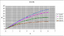
Anyway I have attached a graph of Id vs Vds for different values of Vgs taken from the data sheet. I added a conservative (for safety) curve for Vgs=-3V.
If you have a lab power supply you could probably do the curves yourself.Or maybe Nelson has already done these for us. The data sheet is not good enough for the current range we are interested in.
Attachments
Last edited:
I think the light just turned on about this Vgs thing.
So I will attempt to continue where zenmod left you.
To get a bias around 2A you need a Vgs of somewhere between -5.5V to -4.5V (This is just a guess from looking at the data sheet). The only problem here is that Id changes significantly with small changes in Vgs.
To get a -ve Vgs you need to use fig 7.
Now we don't want to blow up your device so we are going to start real conservatively.
To minimise the dissipation through the device we want to use a Vds around 10V (this is just for safety while determining the Vgs required for 2A).
Second we are going to assume (conservative educated guess determined from data sheet) -5V Vgs will give us 2A bias current.
So you need to change R4 to around 2.5Ohms.
However, to be very safe start with 5Ohms and slowly reduce it to 2.5 Ohms (it might end up being 2Ohms).
Make sure you measure the current each time you reduce the reistance.
You will probably find the current increases exponentially with reducing resistance.
So be patient.
Anyway I have attached a graph of Id vs Vds for different values of Vgs taken from the data sheet. I added a conservative (for safety) curve for Vgs=-3V.
If you have a lab power supply you could probably do the curves yourself.Or maybe Nelson has already done these for us. The data sheet is not good enough for the current range we are interested in.
Thanks for the kind work here. I will give this a shot with the source resistors.🙂
Thanh,
The science project with R085s is now running because of you. Your solution involved less thinking and tinkering on my part, so we got quicker results 🙂
50v loaded supply, 8R cold 120v 300W Sylvania bulb. -4.5 on vgs 4.5 volts measured across 4.7R source resistor.
I tried 10R first, results, but not great, would not light up a 300W bulb, but would a 60W bulb. 2.2R resistor still sounded distored, , about -2.5v vgs.
Enough playing for now, but this looks promising. I kept lowering the source resistor, which did not help....
Initial sound impression - sounds like the R100! Go figure.
The science project with R085s is now running because of you.
Your solution involved less thinking and tinkering on my part, so we got quicker results 🙂50v loaded supply, 8R cold 120v 300W Sylvania bulb. -4.5 on vgs 4.5 volts measured across 4.7R source resistor.
I tried 10R first, results, but not great, would not light up a 300W bulb, but would a 60W bulb. 2.2R resistor still sounded distored, , about -2.5v vgs.
Enough playing for now, but this looks promising. I kept lowering the source resistor, which did not help....
Initial sound impression - sounds like the R100! Go figure.
Hey guys,
Our local guru, Tonywong got it too!!
Much higher voltage used and using 2ohm source resistor.
Got the opportunity to check it out last evening. Its better than Ixys, for sure. Cleaner, clearer, more separation, better highs, etc. Almost every hifi sound attributes known, has improved when we A/B both R085 and 20N50. Its a worthy change.
At the same time, we played around with the output cap. Panasonic FC, Elna starget, slimicII, Nichincon gold tune, etc. Guess who won? *hint: Mr Pass's favorite cap.
Forgot to mention, the amount of changes detectable in changing output caps is comparable to changing from Jfet to Mosfet..... To me... its a real audible improvement when both factors adds up.
I must thank Mr Nelson Pass for guiding us into this point in his article.
Last edited:
Forgot to mention, the amount of changes detectable in changing output caps is comparable to changing from Jfet to Mosfet..... To me... its a real audible improvement when both factors adds up.
Not to mention changing the source resistor to a metal film 1% ; is another step forward to a good , very good sound .
Thanh,
The science project with R085s is now running because of you.
50v loaded supply, 8R cold 120v 300W Sylvania bulb. -4.5 on vgs 4.5 volts measured across 4.7R source resistor.
I tried 10R first, results, but not great, would not light up a 300W bulb, but would a 60W bulb. 2.2R resistor still sounded distored, , about -2.5v vgs.
Enough playing for now, but this looks promising. I kept lowering the source resistor, which did not help....
Initial sound impression - sounds like the R100! Go figure.
I think I feel just as happy as you do about your success (This is the first time to my knowledge that I have actually helped someone solve a problem).
To lower the source resistor further (ie increase the bias current) you need to either increase your supply voltage, or reduce the load at the drain (ie reduce light bulb resistance).
So to double the bias current you will first need to half the light bulb resistance.
So if you have one in series, put another in parrallel.
Or if you have 2 in series, reduce it to 1 in series.
Once you have reduced the load at the drain you should be able to reduce the source resitor further thereby increasing your bias current.
I think nelson suggested going for around 2A bias current.
If you have a 50V supply then you want around a 12Ohm load at the drain, which would give you a 24V drop (ie with 2A bias) which will leave you with a Vds of 26V and therefore 52W of dissipation through the Jfet, which should be fine for these new Jfets.
Before you do any of that can you confirm how many light bulbs you are using per channel and how they are arranged and what your power supply voltage is.
From what you have stated it looks like you have a bit under 1A bias current (lets say 1A to keep it simple) which will mean you have an 8V to 10V drop (as a guess) across the 8R cold light bulb so you have a Vds of about 40V. Can you measure the voltage drop across your light bulb.
Edit: It would also be good to know what speakers you are using. What is the efficiency and impedance of your speakers?
Last edited:
Well, I've tried a few variations here that work.
I have a 45-0-45 trafo.
If I wire the two hots, I can get 90v ac.. and get over 100dc if I am not being careful.
at ~100v, a 2.2R with a single 4R lightbulb does the trick and sound good.
With a 8R single bulb, 2.2R it does not sound good. Getting close to very distorted sound.
Best sound so far is 45-0 loaded through for about 50-55v dc loaded. Using no cap, 47k resistor gate to ground and a 25W 4.7R resistor, and 4R bulb. It sounds a little bit mellower than the Enhanced mode R100 in this voltage range.
All SemiSouth's have IMO a clean upper mids that bring some extra resolution to a sound stage positioning that I have not seen before.
The IXYS parts may in fact have a more 'balsy' sound to them, dynamic, which may be appealing to many. I think they are different flavored parts. In the D-Lite form factor, I am just beginning to get some results.
In my Mini-A with R100 output, the bugger is pretty good. It's got the most precise soundstage I've had in my system, and very 'atmospheric'. It seems to beat out my F5 clone in some ways. The F5 having a bit less atmosphere, less exact soundstage, but very detailed, puncy and musical.
Hi Tea Bag,
At those very low R it would be worthy to try some pure copper DIY resistors (I have here suitable OCC copper enamelled wire) like -ECdesigns'- honeycomb resistors ( with inductance cancelling and low interwinding capacitance architecture ) like I was planning to do, on a clay body to allow heat dissipation. 😎
Thanks for your reports and good luck.
M.
I am about to start building my De-Lite (thanks to Tea-Bag for the mosfets)
R1 needs to dissipate 20w. I am thinking Alu clad resistor. Should the 47k be the same?
Rob.
R1 needs to dissipate 20w. I am thinking Alu clad resistor. Should the 47k be the same?
Rob.
Excellent Thanks.
Are there any specific tweaks or tips that builders have come across when using the
6n50D2's, or shall I just follow Nelson's schematic.
Are there any specific tweaks or tips that builders have come across when using the
6n50D2's, or shall I just follow Nelson's schematic.
Just reporting some of the experiments that Tony and I did, we wired 80Vac with 2ohm source and one Jfet gave way immediately. Not sure what can be done here. With 70Vac, it too gave way, after sometime, maybe due to the fluctuation in the mains. The drain source voltage is 30VDC at 70Vac.
However, we did some simple comparison at 70Vac and 60Vac, 70Vac sounds ballsier, stronger low mid, more dynamic and more presence. In fact, drain source voltage too affects the sound.
Hi Teabag,
What is the drain source voltage that you have tuned when you played at 90VAC?
However, we did some simple comparison at 70Vac and 60Vac, 70Vac sounds ballsier, stronger low mid, more dynamic and more presence. In fact, drain source voltage too affects the sound.
Well, I've tried a few variations here that work.
I have a 45-0-45 trafo.
If I wire the two hots, I can get 90v ac.. and get over 100dc if I am not being careful.
at ~100v, a 2.2R with a single 4R lightbulb does the trick and sound good.
Hi Teabag,
What is the drain source voltage that you have tuned when you played at 90VAC?
- Home
- Amplifiers
- Pass Labs
- Pass "DeLite" Amp from BAF