anyway - 13E1 tetrode is good enough - 13V/2A6 across filament 😉
Papa sez somewhere something about using tired tube .....
Papa sez somewhere something about using tired tube .....
Yes - and I did think about doing just that! Impatience got the better of me though and I went with the halogen sticks.
Lovely amp though!
Lovely amp though!
Like this 🙂
Sure, Papa ends up in a submarine filled with tube amps.
Submerged to a depth of a thousand feet he is to discover that ZM is also on board, for what will go down in history as the "Serbian (adoption) Experiment".
wakoojaccoo - that was a picture of Heaven
Ultimate OTL tube amp , wires directly to brain ......

Ultimate OTL tube amp , wires directly to brain ......
wakoojaccoo - that was a picture of Heaven
Ultimate OTL tube amp , wires directly to brain ......
In fact, that was an amp. The problem was when it began to oscillate 😀😎
Nevertheless, I enjoy that scene, and building an amp, just for a sake of resemblance to that, would be a pure joy 🙂
Attachments

anyway - 13E1 tetrode is good enough - 13V/2A6 across filament 😉
Papa sez somewhere something about using tired tube .....
Interesting! I have some worn out 13E1's and thought about using their filament as load for a "de lite" variation using the FETs I got from Tea Bag.
just for a sake of resemblance
Back in the valve times i attended a demo that looked a bit like the Phily works.
4-tower Infinity reference standard with banks of Jadis JA200 and JA500 monoblocks, well over hundred 6550 tubes.
Zen surround sound
Aaaaeeh, now it brings sense ...it's a collection of Zen amp's for Audyssey's 9.1 or 11.1 surround sound 😉Like this 🙂
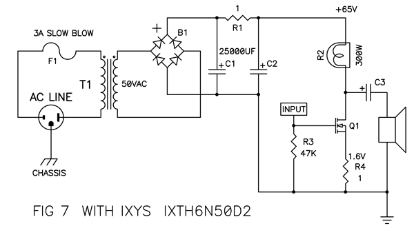
So I dropped in a pair of SemiSouth R085 JFETs into the De-Lite. Emulating the circuit in Figure7 of the article.
It got very low output with default one 300W light bulb. I tried swapping around the 47K resistor between 220R and 120K, no real difference there. I look at it more, and the Drain to Ground voltage was only 2v, from a 50V DC supply when under load.
After some more playing around, including an input cap added, I used a simple 8R total value bunch of sandcast resistors instead of a bulb, and got the gain to sound somewhat normal. Of course these were way underrated and quickly overheated.
I am thinking of using a transformer wired using the secondaries to see if I can get some lower Resistance here with some decent dissipation.
So I am not able to use this as a simple drop in replacement of the IXYS's. Hoping Nelson or someone can chime with some ideas.
So I dropped in a pair of SemiSouth R085 JFETs .....
what is Ub and bias through them ?
seems they're over biased for tried load/bulbs , so voltage sag across load is way too high
either decrease bias ( increase Ugs (minus ! ) ) or decrease bulb resistance
ZM, what is Ub?
1.8v across 1R resistor @ 50v w one bulb, 3.6v with 2 bulbs in parallel.
Bulb resistance for one cold is about 8R.
My amp meter fuse must be blown, or it's over 10A.
To increase -UgS, increase or decrease resistor? I got no love doing that before.
1.8v across 1R resistor @ 50v w one bulb, 3.6v with 2 bulbs in parallel.
Bulb resistance for one cold is about 8R.
My amp meter fuse must be blown, or it's over 10A.
To increase -UgS, increase or decrease resistor? I got no love doing that before.
Ub means Vcc means PSU (voltage) 😉
ok - loking for schematic , without success ..... so - I'll describe dumbest DeLite
resistor from gate to gnd is there to explain dummydumb gate where potential base is
resistor from source to gnd is there to elevate dummydumb source from potential base above gate potential ......... achieving same effect as semi opened vent on your water tap - setting max current through dummydumb jfet
value of hot bulb filament will bring drain of dummydumb Jfet on approx. half of Ub
so - fiddle with source resistor and bulb (filament resistance ) 'till you get max possible current through Jfet , still having bulb type in Papa's DeLite original boundaries ....... and dissipation/drain voltage in these boundaries
OK- while I'm typing this , I remember where I can find DeLite schmtc , so - here it is
whatever Ub voltage you have - try to have 25-30V on drain ....... current through amp at least 2A
it;s really iterative game - setting source resistor and bulb resistance to have all needed parameters - it's sort of licking a big Ice cream - chasing all around , preventing sticky fingers ....
edit:
1V8 across 1R resistor is pretty much as 1A8 through that same resistor ...... at least on my side of Big Splash
dunno for your side ...... anyway - you all must be sort of wakoo - water is spinning backwards in your water closets
editedit: yes - increasing source resistor results in greater -Ugs , and decreasing current through Jfet .....
decreasing resistance of bulb will result in lesser voltage drop across it ....... resulting in greater drain potential ........ resulting in greater current through Jfet itself .....
ok - loking for schematic , without success ..... so - I'll describe dumbest DeLite
resistor from gate to gnd is there to explain dummydumb gate where potential base is
resistor from source to gnd is there to elevate dummydumb source from potential base above gate potential ......... achieving same effect as semi opened vent on your water tap - setting max current through dummydumb jfet
value of hot bulb filament will bring drain of dummydumb Jfet on approx. half of Ub
so - fiddle with source resistor and bulb (filament resistance ) 'till you get max possible current through Jfet , still having bulb type in Papa's DeLite original boundaries ....... and dissipation/drain voltage in these boundaries
OK- while I'm typing this , I remember where I can find DeLite schmtc
, so - here it is
whatever Ub voltage you have - try to have 25-30V on drain ....... current through amp at least 2A
it;s really iterative game - setting source resistor and bulb resistance to have all needed parameters - it's sort of licking a big Ice cream - chasing all around , preventing sticky fingers ....
edit:
1V8 across 1R resistor is pretty much as 1A8 through that same resistor ...... at least on my side of Big Splash
dunno for your side ...... anyway - you all must be sort of wakoo - water is spinning backwards in your water closets
editedit: yes - increasing source resistor results in greater -Ugs , and decreasing current through Jfet .....
decreasing resistance of bulb will result in lesser voltage drop across it ....... resulting in greater drain potential ........ resulting in greater current through Jfet itself .....
Last edited:
dunno for your side ...... anyway - you all must be sort of wakoo - water is spinning backwards in your water closets
Yep, that's the answer 😀 -> Link: Draining in bathtubs and toilets
Last edited:
My amp meter fuse must be blown, or it's over 10A.
Tea-Bag, did you power your Zen up with the amp-meter mounted ? Both the Zen circuit and large capacitors can blow the fuse, because of the high startcurrent.
To avoid blowing a fuse: I'm always mounting a bi-wire over the amp-meter, when starting up. After one second it's runing ( capacitors loaded ) you can remove the bi-wire and the fuse wouldn't blow.

NOT TO DO: I've seen people changing their amp-meter's fuses from a "fast-blow" to a "slow-blow" type, but that's not intended, to be the solution, so don't do that.
Last edited:
Yep, that's the answer 😀 -> Link: Draining in bathtubs and toilets
pssst ..... don't tell them that main reason for direction is certainly in exact angle of tube going to armature ......
the source resistor also provides some degenerative feedback, if i remember correctly, helping to linearize the FET. Make it too big and the sound will suffer. It is really a game of how to achieve the required drain voltage and current for most linear operation. Papa sets it at 1A and 25 V drain voltage for the IXYS part... The JFET will have some different parameters, so you can go check your F1J and F2J for where it's drain is.
Tea-Bag, did you power your Zen up with the amp-meter mounted ? Both the Zen circuit and large capacitors can blow the fuse, because of the high startcurrent.
To avoid blowing a fuse: I'm always mounting a bi-wire over the amp-meter, when starting up. After one second it's runing ( capacitors loaded ) you can remove the bi-wire and the fuse wouldn't blow.
NOT TO DO: I've seen people changing their amp-meter's fuses from a "fast-blow" to a "slow-blow" type, but that's not intended, to be the solution, so don't do that.
No, didn't start it up that way. It's on a variac. It's a fussy VM, eat's batteries. I may have put it together wrong, will need to look into it.
I swapped back the IXYS, and things played normal again. I thought it was a power supply issue. Still not convinced it's not.
I have done the following.
Used a 60W bulb, which appears to have 20R resistance cold, and two in series. Same low signal. Use two 8R 300w bulbs in parrallel to same effect.
I lowered the source resistor to .15R total, no change, although that drops the drain voltage lower. I have not raised the Source resistor any.
These buggers are hard to figure out.

Last edited:
No, didn't start it up that way. It's a fussy VM, eat's batteries. I may have put it together wrong, will need to look into it.
I swapped back the IXYS, and things played normal again. I thought it was a power supply issue. Still not convinced it's not.
I have done the following.
Used a 60W bulb, which appears to have 20R resistance cold, and two in series. Same low signal. Use two 8R 300w bulbs in parrallel to same effect.
I lowered the source resistor to .15R total, no change, although that drops the drain voltage lower. I have not raised the Source resistor any.
These buggers are hard to figure out.
In another forum a guy told about some Mos-Fet's, which not has the same pin-out as described. Source and Gate were switched around from the manufacturer
 ...weird, but after turning it around, his circuit was runing fine.
Could it be something likely, with your Mos-Fet's ?

- Home
- Amplifiers
- Pass Labs
- Pass "DeLite" Amp from BAF