Yes, very similar. And also, you are going with one tube per channel more 😀 OPT is simpler this way, but you need more iron.
One GM-70 per channel is enough for my needs. I wanted all DHT tubes, so, my choice was a little limited. D3A was my second choice, but it's IHT.
I wish you luck with your project. You won't regret it. GM-70 sounds wonderful.
Regards
One GM-70 per channel is enough for my needs. I wanted all DHT tubes, so, my choice was a little limited. D3A was my second choice, but it's IHT.
I wish you luck with your project. You won't regret it. GM-70 sounds wonderful.
Regards
Hi Guys. So I'm doing fitting, it's almost all in there. I know a couple of you are using Rod's boards with GM-70's (Rod, Kevin)...Any way you could upload a pic or two, or at least dimensions, on your heatsinks for the boards? I can mount them to chassis and be fine, but I have room and might be able to give them their own, which I would much prefer. just want to see what size others are using since I know both of you at, least, have long working amps. Thanks guys,
Loren
KB2WYL
Loren
KB2WYL
Hi Guys. So I'm doing fitting, it's almost all in there. I know a couple of you are using Rod's boards with GM-70's (Rod, Kevin)...Any way you could upload a pic or two, or at least dimensions, on your heatsinks for the boards? I can mount them to chassis and be fine, but I have room and might be able to give them their own, which I would much prefer. just want to see what size others are using since I know both of you at, least, have long working amps. Thanks guys,
Loren
KB2WYL
I think you should inform what voltage you have before Rod's boards. This will say how big heatsink is needed.
Thanks Vladimir...I didn't even think to, and yes you're right...I wasn't thinking of it but I'd bet it's about the same as Rods boards, as he says that this is optimal, but it is 24.9 volts...so 4.9x3=15W and yes I can figure it out like this, but I would still like to see some other implementations....for what it's worth any of you running 845 at 10V with a 14.* supply for Rod's boards, same dissapation...I'd love to see. Again I can look up pics but I enjoy the visual with the verbal "this works for me"
Thanks again,
Loren C.
KB2WYL
Thanks again,
Loren C.
KB2WYL
At 25V input the power transistors burn:
3.0A x 4V = 12W
If the heatsink is 30°C unheated, and we try to keep it to 60°C maximum:
ΔΤ = 30°C, P = 12W, heatsink should be about 2K.W-1 [ = °C per Watt], allowing a margin.
It’s often sufficient to make your own heatsink, either with the top plate of the amplifier, or with some 3mm (1/16”) Aluminium, (thicker is better though), and exposed to the outside air. For example I tested my GM70 filaments running 3.3A, mounted on some 3mm Aluminium, 275mm x 125mm (11" x 5") area. The ΔΤ measured about 30°C, mounted vertically in free air. Make the area a little bigger, if air-flow is impeded.
For those preferring to use a catalogue heatsink:
Best Choice: Fischer Elektronik SK 04/75 SA (1.9°C/W). Gives only about 23°C rise at 12W. It’s 97mm/4” wide, 75mm/3” high, with 25mm/1” deep vertical fins. Having the fins vertically oriented improves convection, of course!
Lots of other vertical-fin sinks on the Fischer Elektronik catalogue, to achieve other thermal resistance values.
SK 04/75 SA FISCHER ELEKTRONIK, Heat Sink, Standard Extruded, Black Anodized, TO-3, 1.9 °C/W, 25 mm, 97 mm, 75 mm | Farnell element14
These are European parts though. I don't seem able to see accurate U.S. pricing on heatsinks for Digikey & Mouser. At Digikey, the Wakefield sink 345-1206-ND should provide enough cooling for 2-tubes worth of regulators, but the high price shown for UK delivery probably accounts for its weight. Wakefield and Aavid Vertical-fin sinks remain good choices though - rated 1-2°C/W.
In many industrial cities, Alu extrusions shops often make heatsinks. Might be worth calling to see if they have local sales, or even some low cost blemished parts.
Hi Loren! The other way to go: Cut out some 3-4mm thick Alu 14" x 3", or whatever the area of the rear-side of your chassis. Then add some small vertical-fin sinks (at the Regulator positions) to add to this 'heastink-plate' to keep the temperature low.
Thanks so much Rod. I think I'll have to go with just the Chassis. It's just too good of a material not to use. On these amps the chassis sides are made out of U-angle aluminum, which is 4mm thick at the thinnest spot (maybe even thicker) abd up to almost a cm thick in the corners of the "U". I'm thinking I'll mount right to it. The top plate would work too, but then I get residual hear from the gm70s and the boards won't be mounted with components facing up like I want...I like your idea of incorporating the sides AND heatsinks, I had thought of that as well. Mount to sides and then bolt on a heatsink on outside of chassis where the boards are.
It's heavy, of course, and I'm having to do some serious examination and figuring, but it is all going to fit just fine which is nice. I had thought about moving just the heater supplies off chassis but these things are already so large I don't want them to each have ANOTHER chassis to go with them.
Thanks again!
Thanks so much Rod. I think I'll have to go with just the Chassis.
This is what I did, but I used aluminum plates as Rod suggested.
Mine are used for 845 tubes, but I imagine I'd be dissipating similar heat as you will need to.. I've got a 14.5V supply, and the filaments run at 10V / 3.25A.. So 3.25 * 4.5 = 14.63W
I got some 1/2" thick aluminum plates that are 4" x 8". So I have those plates mounted on either side of my chassis (which is 1/8" aluminum). And the regulator boards mounted to those plates.. I've run the amp for many hours at a time, and the temperatures never get very high.
Plates, something like this http://www.ebay.com/itm/500-1-2-AL-...176340?hash=item234e663494:g:JEYAAOSwxYxUwm8N
There are so many options for plates on ebay though..
Last edited:
Thank you. I'll keep the plates in mind...since my chassis is already made though I can't use them like that....see one thing that confused me was Rod saying you could mount to underside of top plate...doing that, there's no way that the power resistors don't radiate heat onto the board, which he said not to do. Plus, adjusting the regulators would be a PIA...so what I'm thinking is Ill bolt a chunk of 1/2" vertically, to the top plate. Think if you knelt down and looked straight at the amp, level with top plate, the piece I'm bolting on under the top plate would make a "T". The top plate being horizontal part of "T" and my piece being the vertical part. Then I can mount both regulators to that (offset a little). So I. The end they have a "T" heatsink where vertical part is say 1/2"x4"x5" and horizontal part it the whole top of chassis, which is all 3mm AL (about 15"x21"). That oughtta do it. Right Rod? Then adjustment is easy, put amp on side for a minute and you can get at stuff easily.
Thanks all
Thanks all
Thank you. I'll keep the plates in mind...since my chassis is already made though I can't use them like that....see one thing that confused me was Rod saying you could mount to underside of top plate...doing that, there's no way that the power resistors don't radiate heat onto the board, which he said not to do. Plus, adjusting the regulators would be a PIA...so what I'm thinking is Ill bolt a chunk of 1/2" vertically, to the top plate. Think if you knelt down and looked straight at the amp, level with top plate, the piece I'm bolting on under the top plate would make a "T". The top plate being horizontal part of "T" and my piece being the vertical part. Then I can mount both regulators to that (offset a little). So I. The end they have a "T" heatsink where vertical part is say 1/2"x4"x5" and horizontal part it the whole top of chassis, which is all 3mm AL (about 15"x21"). That oughtta do it. Right Rod? Then adjustment is easy, put amp on side for a minute and you can get at stuff easily.
Thanks all
I think I understand what you're saying, but would the only contact between the 1/2" plate and the top plate of the chassis be the edge of that 1/2" plate? I wonder if there would be enough heat transfer doing it like that..?
You can't mount the 1/2" plate on the side plate of the chassis? So that the wide edge of the 1/2" has full contact with the chassis?
Btw, I added a pic of how the 1/2" plate is mounted in my chassis..
I guess it's probably more like a 4" x 6" piece. There are vent slots above the regulators in the top plate of my chassis which allow heat from the resistors on the regulator boards to escape the chassis, and also give enough room for me to adjust the voltage while the amp is closed up. I also put little test points on the top plate which I can measure filament voltage from.. Maybe overkill, but I really didn't want to have to move or open the chassis at all to measure / adjust the filament voltage.
You can see the one side of the amp chassis, and there's another plate like that on the other side of the chassis.
Attachments
Last edited:
Hmm...ok I had thought of that, but my thought was that it would be hard to do the holes like you did. If you look back in this thread you can see my chassis. The sides are made out of "U Channel" AL. So at the top and in the corner you not only have top plate but you have the U channel, and it's about 3/4" thick. Drilling slots, or even a hole for adjustment, I thought would be hard to make them look halfway decent.
If this idea doesn't work then I'm game for your idea though, definitely more then enough Heatsink would be there. Heck I wouldn't even need the spreader bar on my 4"" thick at the center, and 1/2" thick at top, side pieces.
But I want to hear some other opinions on the transfer with my "T" idea. I was looking at my stock of heatsinks this morning when I noticed that a few of them are made like this. You have a thin piece of bar that has a Christmas tree arrangement of multiple "t" pieces above and below the bar. For example there are these SCR's that come out of a huge power supply. I'm sure they got ridiculously hot. They are mounted on a heatsink where no single part of it is thicker than 3mm, but it is big and branches out again and again (think vertical 3mm thick bar with horizontal 3mm thick pieces above and below component). If it works for these heatsinks, and a lot are like that, it should work for me.
Especially because I would be drilling through the top plate and burying multiple bolts down into my vertical piece of bar, I think the heat transfer would be ok. It's like electricity, AL is an extremely good conductor.
Thanks much for the pics I really appreaiate it.
Hmm...ok I had thought of that, but my thought was that it would be hard to do the holes like you did. If you look back in this thread you can see my chassis. The sides are made out of "U Channel" AL. So at the top and in the corner you not only have top plate but you have the U channel, and it's about 3/4" thick. Drilling slots, or even a hole for adjustment, I thought would be hard to make them look halfway decent.
If this idea doesn't work then I'm game for your idea though, definitely more then enough Heatsink would be there. Heck I wouldn't even need the spreader bar on my 4"" thick at the center, and 1/2" thick at top, side pieces.
But I want to hear some other opinions on the transfer with my "T" idea. I was looking at my stock of heatsinks this morning when I noticed that a few of them are made like this. You have a thin piece of bar that has a Christmas tree arrangement of multiple "t" pieces above and below the bar. For example there are these SCR's that come out of a huge power supply. I'm sure they got ridiculously hot. They are mounted on a heatsink where no single part of it is thicker than 3mm, but it is big and branches out again and again (think vertical 3mm thick bar with horizontal 3mm thick pieces above and below component). If it works for these heatsinks, and a lot are like that, it should work for me.
Especially because I would be drilling through the top plate and burying multiple bolts down into my vertical piece of bar, I think the heat transfer would be ok. It's like electricity, AL is an extremely good conductor.
Thanks much for the pics I really appreaiate it.
Yea, I wouldn't have been able to pull off cutting slots like that myself.. I had some CNC work done.
Maybe the T idea would work, I don't really know though.. If it were me, and I were attempting that option, I'd probably go with a pretty thick plate though.. Maybe you could go like 3/4" or even 1" thick..
I dunno.. I'll stop commenting now I think. I'm sure someone else can give a more educated comment.
No need to stop commenting All good ideas and info. I had a half hour this morning so I went out and gave it one more try. I hadn't thought I would have room on the sides either, but a little re-arrangement of things and I got it. Now I can mount them on the sides, and have them facing up. As far as the ventilation, it's pretty good already because the top plate has many, many spots, but I may drill holes directly above as you did (thanks again for that pic). This takes away worry about the heatsinking, as the sides are more than adequate size, even without any spreader bar. I may still use one, just because I can and it can only help, but either way I finally got the placement of everything. Now that I know it all fits I can get back to plywood, get everything hooked up for a test run.
thanks!
thanks!
Attachments

No need to stop commenting All good ideas and info. I had a half hour this morning so I went out and gave it one more try. I hadn't thought I would have room on the sides either, but a little re-arrangement of things and I got it. Now I can mount them on the sides, and have them facing up. As far as the ventilation, it's pretty good already because the top plate has many, many spots, but I may drill holes directly above as you did (thanks again for that pic). This takes away worry about the heatsinking, as the sides are more than adequate size, even without any spreader bar. I may still use one, just because I can and it can only help, but either way I finally got the placement of everything. Now that I know it all fits I can get back to plywood, get everything hooked up for a test run.
thanks!
The main reason I used the heat spreader bar is because of the note in Rod's document about startup conditions..
He says for transmitter tubes like 845 or GM-70 the thick aluminum spreader bar is "useful in dealing with the startup thermal pulse - a cold filament shows low voltage drop, and the supply voltage is applied across the FET Q5 at cold start."
Actually I was just thinking about how I need to post. I have fit it all in a mock-up, and tested separately. Right now I am in the process of installing everything on the chassis proper. I will post pics in an hour or two. Thanks for the interest!
well
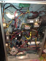
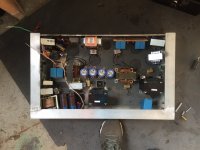
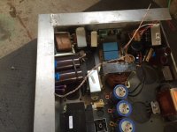
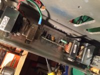
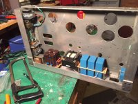
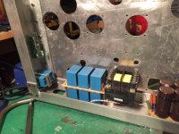
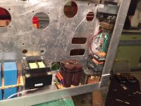
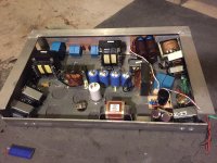
I've been making progress. Here's the pic where I fit everything in. It's the one I've been using to go back and put everything in with actual fasteners and spacers etc. And, a few pics of where I am at right now. The front end transformers and chokes are in, Rod's boards and the spreader bars are in. The HV capacitor bank is in, as well as one of the HV caps that stands alone. One of the heater transformers is in, and the other has been drilled for. I'm about half way. It's hard because there is plenty that has to be put in, drilled and attatched, and then removed again to facilitate the rest of the construction. But, I feel like it was a good useage of space and that things are not TOO crowded with all of it in there. Pretty good, I think, for single chassis...especially for PSE. I'll try to be more active with the thread, just been really busy with work, as well as going back to school for some welding classes. Thanks again,
I've been making progress. Here's the pic where I fit everything in. It's the one I've been using to go back and put everything in with actual fasteners and spacers etc. And, a few pics of where I am at right now. The front end transformers and chokes are in, Rod's boards and the spreader bars are in. The HV capacitor bank is in, as well as one of the HV caps that stands alone. One of the heater transformers is in, and the other has been drilled for. I'm about half way. It's hard because there is plenty that has to be put in, drilled and attatched, and then removed again to facilitate the rest of the construction. But, I feel like it was a good useage of space and that things are not TOO crowded with all of it in there. Pretty good, I think, for single chassis...especially for PSE. I'll try to be more active with the thread, just been really busy with work, as well as going back to school for some welding classes. Thanks again,
Attachments
Ok Guys
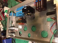
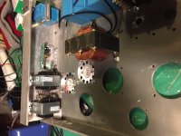
Trying to be better about posting...So tonight made little more progress. Mounted both of the filament transformers for the 6CJ3s (They each get their own). Also mounted both of their 9-pin sockets (In socket spacers for ventilation), and since one of the sockets shares a bolt with one of the GM-70 Filament supply chokes, I mounted that choke as well. Just posted one of the chassis tonight seeing as though the other is the same, just a mirrored image. I think it'll be neat when they are done that whether they are mirrored from the center, or opposite coming from left to right (or right to left), that there will be that symmetry. I Like that look more than 2 of the same, and much more than 2 of the same when they are placed directly side by side. This way you can place the chassis directly next to each other and it ends up looking like one giant chassis, with close to perfect symmetry (no CNC here but I am measuring every part placement within 1/8").
Rod, if your reading still, there's no problem having the boards powered without any load is there? When I get to the wiring stage, it would be much easier to wire in the regulators and have them powered while I'm doing final testing on b+, bias, etc.. I didn't figure they cared much if the filament side is left open circuit, can't imagine why they would, but figured better safe....
Thanks all
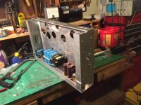
Attachments
That'll be pretty crowded in there, plus 2x GM-70 per chassis. I've said it before, it will be VERY hot.
Looking forward to see the end result! 😉
Looking forward to see the end result! 😉
I agree about both, but I am hoping not to detriment.
On the crowding, yes, especially versus most of my builds. But I have seen so many working transmitting tube designs, even so many PSE designs lole mine, which are even more crowded, and work on a regular basis. Yes most have a bit more room, but many are at least as crowded as most use smaller chassis than mine and really the only parts taking up space for the second Gm-70 vs. an SE amp, are one more heater transformer and one more choke. Yes they're both big, but not as much as many chassis are smaller. Either way your right something to look out for and I'm glad I don't have anything else to try to fit .
As far as the heat, I'm trying to take what steps I can to reduce it as much as possible. Everything under the hood is overrated to reduce heat. 25w resistors, 10a heater transformers, giant heat sinks for the regulators, Etc. Etc...but again, you're right lots of heat. It's why I went With those vented socket spacers, vent holes above the regulators, the GM70 sockets will not only be vented but also raised 3/4" above the rest of the chassis. Also if you see in the front the chassis is only half height, that will probably be screening of some sort, possibly even small silent fans, we'll see.
Anyway, yep I agree, it'll be interesting to see the final incarnation of this beast.
Thanks
- Status
- Not open for further replies.
- Home
- Amplifiers
- Tubes / Valves
- Parallel GM70 Amp