Yes, the raw dc supplies should always be separate, except (e.g.) in a PP pair where the each DHT's Filament + terminals are guaranteed to be at the same dc voltage - as when they are connected together. A separate regulator should be used for each, though.
Kevin is correct: any bias method is good, the Regulators can float hundreds of volts above ground, if need be. The Raw dc supply must always float, so there will be no leakage, provide the transformer isolation is normal (i.e. good for kV-level testing), and the heatsink interface is made properly (mount the transistors with clips, for high voltage isolation).
well Hello Rod, What I have been thinking about is to use my large external power supply I believe its 28v passive regulation anyways then run these into your regulators separate so it feed each tube individually, I cant understand why this may not work?
Lawrence
Hello Lawrence, Shared raw dc is only possible if (Filament +) on each DHT is connected together.
If the dc voltage on Filament + of two Regulators is different, a leakage current will flow from one filament to the other through the raw dc. The current will be in part drawn from the B+ (HV) supply, and will noise unwanted noise and biasing shifts.
So if you can connect the two filament + sides together, all will be well. BTW, The Filament - (negative) sides must not be connected together, or there will be crosstalk of the plate/anode current of the two DHTs. Only the positive sides.
Hello Lawrence, Shared raw dc is only possible if (Filament +) on each DHT is connected together.
If the dc voltage on Filament + of two Regulators is different, a leakage current will flow from one filament to the other through the raw dc. The current will be in part drawn from the B+ (HV) supply, and will noise unwanted noise and biasing shifts.
So if you can connect the two filament + sides together, all will be well. BTW, The Filament - (negative) sides must not be connected together, or there will be crosstalk of the plate/anode current of the two DHTs. Only the positive sides.
I think I will contact you offline and discuss?
Lawrence
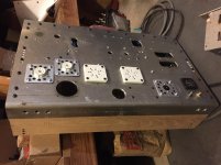
Hey guys, been saying for a week or two now that I would upload a pic. Haven't made too much progress lately. I'm building a shed out back. This will allow me to take the garage attatched to my electronics workshop, and actually devote it to woodworking/welding. As you know, with amps of this size, an hour here and there isn't much. But I did get few things done since last. The supplies for the heaters are all in. Rods boards already were last post, but now the resistors are mounted on chassis (heatsinked) and the caps are in. First RC cap in the choke input supply notwithstanding, but that's just a couple big polys from R to neg on the bridge. Power switch is in. AC receptacle is in. Main fuse is in. And the biggest thing, the wood. Solid oak that I drilled and countersunk. Then tapped the holes in the chassis. Each piece has 5 M5 hardened bolts. They only see vertical weight anyhow, so they could handle hundreds of pounds fine. But being oak they can take the whole weight of the amp even if you were to pick it up like a briefcase. And see how the side pieces are set in? That lets you pick up the amps from the side without reaching fingers under the amp. Plus the extra height, great for cooling. I had this idea all along, but it worked out a lot better than I thought it would, and so I'm pleased with it. Hopefully more to come soon. Thanks all
Attachments
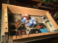
Nice that you got some vent holes above those filament regulators, and possibly you've got access to the trimpot on the boards to be able to adjust filament voltage from the top side with a small screwdriver through one of the holes?
One thing I did on my amp was to put test points for the filaments somewhere on the outside of the chassis as well, so that I could measure them without opening the amp up, to make sure they're settled in at the right voltage after hours of running, and then if you can also adjust those trimpots from the top side with the chassis closed, that's really handy as well. Especially handy when changing tubes.
I think I used something like these for the test points
http://www.digikey.ca/product-detail/en/pomona-electronics/4773-9/501-1453-ND/736982
Last edited:
No problem with individually rectifying on dual secondary transformers, I have done it from time to time; the important thing is not to exceed the rating of the individual windings.
Yes, please use the email option, when you click my name - PMs are a hassle!
 There is no email option, it was disabled long ago due to security issues.
Hi Guys.
theoj,,,,,yes I can acess the pot topside. I set it up to use one of those insulated flatheads, the all plastic type. Once you know where it's at, it's pretty easy to find, but this prevents chance of damaging something. What I might even do, at some point, is solder on a tube going from the vent hole that is used, that goes down just about to the trimpot, so that the insulated screwdriver has no choice but to be in the right spot.
As for the test points, yup agree as well. It's funny you sent that link, I have the exact same ones only in red/black. I use them when I'm flipping an amp for sale and want to quickly add bias test points for the new owner.
Kevin, I assume you were referring to my earlier post, where I said I thought the OP was talking about dual rectification on one transformer....I meant on one winding...yes dual winding's are fine. One thing that I have found about using dual winding's though, not for heaters but once in a bias supply, was that I had to be mindful of phasing. The filtering was apparently not enough, and the ripple getting through in opposition to, or in phase with, the HT ripple caused an oscillation that took me days to trace to that cause....
What I might even do, at some point, is solder on a tube going from the vent hole that is used, that goes down just about to the trimpot, so that the insulated screwdriver has no choice but to be in the right spot.
This is an excellent idea! I'm definitely going to implement this, rather than fiddling with a flashlight and screwdriver.
Thanks...yeah i like it, you can make the tube as long as you want so that it drops out just right above the trimpot...I got the idea from those old ohmite type pots that had that sort of connection you screw on to the pot and it recesses it into the chassis...you know the ones, they're hex holes and you have to tighten them with a big 10mm hex driver...
On a side note I still don't know what those are called, and haven't been able to find any but for the ones I pull...
On a side note I still don't know what those are called, and haven't been able to find any but for the ones I pull...
Hi,
did you manage to finish your project?
I'm working on modifying my B+ PSU ... I have in mind CLCLC filtering. 16uF 1.6kV PIO and 5H chokes.
Regards
did you manage to finish your project?
I'm working on modifying my B+ PSU ... I have in mind CLCLC filtering. 16uF 1.6kV PIO and 5H chokes.
Regards
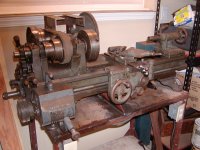
How funny, I was just perusing the forums a day ago, thinking how I need to post. Haven't finished, although all the boards (power supplies, biases, filaments, etc etc) are all finished. Chassis are all drilled and finished. Just need to put it together! Been busy with work and school. I ended up taking 2 classes this semester, another welding and a machine technology. It's been eating up my free time. But I can feel the urge of electronics coming back on, especially with summer and class ending. Just got this little guy yesterday. It's nice knowing that the next time I need some oddball tube socket, nice plate cap, whatever, that I can just make it. Higher quality and free other than time.
Attachments
Hi,
did you manage to finish your project?
I'm working on modifying my B+ PSU ... I have in mind CLCLC filtering. 16uF 1.6kV PIO and 5H chokes.
Regards
Since I have already switched to applying high voltage cap multypliers as B+, I have some spare 2000V 100uF film caps in metal cases, designed for pulse current applications. All is good with them, except for space needed. Tell me if somebody interested.
Since I have already switched to applying high voltage cap multypliers as B+, I have some spare 2000V 100uF film caps in metal cases, designed for pulse current applications. All is good with them, except for space needed. Tell me if somebody interested.
100uF 2kV caps are BIG! What's their dimension?
Regards
100uF 2kV caps are BIG! What's their dimension?
Regards
They are 86x111x141mm size, 2,145kg weight. Enclose datasheet.
Attachments
They are 86x111x141mm size, 2,145kg weight. Enclose datasheet.
If they were 86 x 81 x 141 (like 80uF 1.6kV) I would have enough room for them, but for these, there just isn't 😕
If they were 86 x 81 x 141 (like 80uF 1.6kV) I would have enough room for them, but for these, there just isn't 😕
Yes, this is the problem, I usually was forced to build an external power supply with them.
I have some 20uf 1.6kv that are the same way. These are made for more amperage, but still too large like yours. This is why I went with the Epcos. They (Phillips as well) have some very compact 1.8kv that can be paralleled. And/or series paralleled depending on the application.
Loren
Loren
- Status
- Not open for further replies.
- Home
- Amplifiers
- Tubes / Valves
- Parallel GM70 Amp