Nontheless, very interesting project. I wish you luck. Try to wire everything as neat as possible.
Regards
Regards
<cut>
Rod, if your reading still, there's no problem having the boards powered without any load is there? When I get to the wiring stage, it would be much easier to wire in the regulators and have them powered while I'm doing final testing on b+, bias, etc.. I didn't figure they cared much if the filament side is left open circuit, can't imagine why they would, but figured better safe....
Thanks all
It's probably best to disconnect it. Especially if you have choke-input supplies, the unloaded voltage will rise substantially, with a GM70. The transistors are all rated for 50V+, but cap C1 is 35V rated. It has a current limited feed, so it will OK, but since I think you use choke-input supplies, it feels a bit uncomfortable to risk over-stressing it.
The silent fans are well-worth looking at, BTW. I recently replaced the screeching fan in my oscilloscope, and was delighted to find that the (low cost) Coolink SWiF2 cannot be heard without putting an ear within 4 inches of it.
Thanks Rod. Alright. The one design mistake I've made so far is that the front panel has holes for power switches (2) on the left AND right of both chassis, so 4 in total...maybe I'll fill them with a switch for the heaters, wouldn't be bad in the end to have them turn on first anyhow. Yes, Raw DC choke input: (rc)LCRC, 25.2V. The silent fans I think are nice too. They've come a long way in the last few years. Since most of the heat is obviously top side with the GM-70 and 6CJ3 it's not a bad idea to force a positive air situation under the hood, in whic case the convection from all that heat top side will help there be a good constant flow from outside to underneath to up top.
The wiring I plan on making as neat as possible, why I chose all the boards instead of all point to point. HV will be on test lead super thick silicone and the rest on solid conductor silver 16878/4E 18awg Teflon.
Thanks all
The wiring I plan on making as neat as possible, why I chose all the boards instead of all point to point. HV will be on test lead super thick silicone and the rest on solid conductor silver 16878/4E 18awg Teflon.
Thanks all
ok
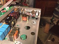
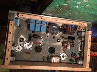
got some more done. The rest of the chassis is done. All solid oak. No, there is nothing that even gets warm mounting to it, and remember with amp flipped it's all on bottom. I secured it by drilling and then counterdrilling the oak. C-clamped that to chassis and then drilled chassis. Then tapped those holes. So each piece is attatched with 5 M5 bolts into 3/8" of hardened AL (yes, there is such a thing as hardened Aluminum, and that's what the U beams which make up the sides of my chassis are). Also drilled the holes for the 15Hy chokes for the GM-70 bias supply, which are going topside. Also mounted the LL2756/25ma interstage transformers, and the RCA input, and the 250ohm D3a bias adjustment pot. Also mounted the bridge rectifiers for the choke input supplies for Rod's regulator boards. I'm getting close to the point of having to start wiring the couple of spots which will be buried by other components. Like the input RCA to the D3a socket. The boards for D3a Bias and D3a DC filament will go on spacers above those two wires, which would make it impossible to get in there with a soldering iron. It's busy in there, yes, but I'd like to think I'm doing alright so far at keeping it neat. Down the road in the future, if something needs to be changed, at least 80% of the components (and all the ones that have a "lifespan") are just 4 bolts, easily accessible from the outside, and that board is out.
Well, I'll post more soon. Next will be drilling all the holes for the capacitor clamps, for the RC filter and CRC filter parts, of the "(rc)LCRC" regulator board supplies.
Thanks for looking
Attachments

Looking good!
What type are the bridge rectifiers? Take care if using ordinary PN type for the filament raw dc - compared to Schottky, these can get hot, and make some noise. Though with choke-input, these differences are much lowered.
What type are the bridge rectifiers? Take care if using ordinary PN type for the filament raw dc - compared to Schottky, these can get hot, and make some noise. Though with choke-input, these differences are much lowered.
Hi Rod. They are KBPC5010, 1000v50A. I had a few things on hand (including Schottkys) but I went with these because
a.) The package, easy mounting and heatsinking to the 4mm plate which is the top of the chassis. And the physical size vs heat, low stress
b.) Being choke input and having the regulators I didn't figure noise would be an issue
c.) Being 1000v 50A they drop almost 2V which is great because I end up right at 25.6V (without having to use any more than .3R in the CRC)
I will probably snub them anyhow, just because it is so easy (same goes for a lot of the different PS caps in here with bypasses). A lot of that it's doubtful wether there is any sonic difference, in this particular setup, but I might as well.
Agree?
Thanks again
I will probably snub them anyhow, just because it is so easy (same goes for a lot of the different PS caps in here with bypasses).
Yes, Loren, this is highly recommended, since heater supply subsystem is sitting in the signal chain. Maybe, after snubbing, some additional RC stage with neatly shunted C would be useful.
With SMPS for heater, I used 5 stage RC (cutoff frequency around 40-50kHz).
Hi Loren
Yes, you have reason it out well, especially since you need the extra drop. I'd probably take care to keep the rectifier cables nice & short, to prevent noise EM-coupling to the signal wiring.
If you need lower drop after testing, the schottky STS1545FP is well-rated and mounts directly (isolated package).
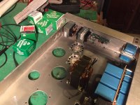
that's what I thought. I have an RC stage after the Bridge (snubber), then the choke, then CRC. After that, Rod's boards. With neatly shunted C in every part of that (across the RC and across both the C in the CRC), and with then the Regulator Boards which further block any switching noise, I think I should be ok. Actually I'm sure I'll use some of the caps I got from you Vladimir 🙂. And yes Rod, if it turns out in the end that I have a volt or two to spare then sure, I'll change out to Schottkys. But shouldn't be as I did pretty extensive testing before i started installation. Since these have so much under the hood, being PSE, I want everything to be lowest heat possible. Hence the 9A heater transformers, and the R's only being .3r. If you look in the pic, the one bridge you can see right in front of one of the transformers. Other one, you can see the holes where transformer goes right below it. Wires from AC from transformer to the bridges will be all of about 2.5", and that's just because of the transformer height. After that, about 2" to the rc filter. Only after the DC goes into the choke, and after the CRC after that, do the wires get to be 6" or so just to get them over to the Regulators. And 6" to get from regulators back to tubes. The CRC will only be seeing just over 1.2A ripple, so those 10,000uf should last for a while, as they are rated 8.8A (each) .
Also, the actual cathode R (because remember I'm attenuating cathode a little bit for balance) is going to be also only an inch of wire>resistor> variable resistor,>ground. And as far as the grounds for all of these caps, and the cathode (as well as all the other grounds in system) I am going to do a ground bus. For heaters one that comes from negative tab of bridge. For GM-70 comes from center tap. etc etc etc and then all connected to chassis in one spot (except for heaters, of course)
Thanks guys, I really appreciate the comments
Actually I'm sure I'll use some of the caps I got from you Vladimir 🙂.
One should remember, that diode recovery noise falls into high MHz region, and in your RC just after bridge I would recommend C shunting with silver-mica 1000pf, 10000pF, polypropylene 1uF. Also I suppose that you put 0,1uf-10 Ohms chain on EACH diode in the bridge.
I would rather use schottky, and put additional RC for suppressing excessive voltage.
So you really think that the bridge will make that much noise? I was understanding it as diode noise used to be far more of a problem with older PN diodes. And with Rod's. boards as well? If it were just a normal filtered D.C. supply straight to the heathers then I wouldn't question that yes, use Schottky. But for this, you still think it (noise) could be an issue?
Thanks,
Thanks,
My Regulators will remove (almost) any such noise in the conducted path.
The remaining hazard is only that EM-coupling of noise-pulses into signal wiring, or other parts. The recovery pulse is a large current, with only a small voltage showing up, so this means a low-impedance B-field. Short cables to the bridge will help, and longest distance to the susceptible parts/cables, and loop-area of the grid-cathode circuits kept minimal. DACs should not be placed near to the amp's transformers. The schottkys will always emit lower noise, though, if in doubt. Standard bridges usually specify nothing about recovery time, because it's not usually relevant.
The remaining hazard is only that EM-coupling of noise-pulses into signal wiring, or other parts. The recovery pulse is a large current, with only a small voltage showing up, so this means a low-impedance B-field. Short cables to the bridge will help, and longest distance to the susceptible parts/cables, and loop-area of the grid-cathode circuits kept minimal. DACs should not be placed near to the amp's transformers. The schottkys will always emit lower noise, though, if in doubt. Standard bridges usually specify nothing about recovery time, because it's not usually relevant.
Rod
Rod, are you able to self cathode bias with your regulators?
Can you feed 2 regulators with one supply?
Thank you
Lawrence
Rod, are you able to self cathode bias with your regulators?
Can you feed 2 regulators with one supply?
Thank you
Lawrence
Any form of bias is possible with Rod's filament regulators, and no you cannot use the same supply to feed two regulators, they need to be fully isolated from each other.
....... and no you cannot use the same supply to feed two regulators, they need to be fully isolated from each other.
Are you sure?
Quite, and will let Rod expound on why it's not a good idea. (They are floating except where one side of the filament is connected to ground or if filament current derived bias is used in which case the whole thing floats on the IR drop of that resistor)
Yes, the raw dc supplies should always be separate, except (e.g.) in a PP pair where the each DHT's Filament + terminals are guaranteed to be at the same dc voltage - as when they are connected together. A separate regulator should be used for each, though.
Kevin is correct: any bias method is good, the Regulators can float hundreds of volts above ground, if need be. The Raw dc supply must always float, so there will be no leakage, provide the transformer isolation is normal (i.e. good for kV-level testing), and the heatsink interface is made properly (mount the transistors with clips, for high voltage isolation).
Kevin is correct: any bias method is good, the Regulators can float hundreds of volts above ground, if need be. The Raw dc supply must always float, so there will be no leakage, provide the transformer isolation is normal (i.e. good for kV-level testing), and the heatsink interface is made properly (mount the transistors with clips, for high voltage isolation).
I am wondering if they were referring to dual rectification off of one transformer (dual secondary). Still not adviseable, but I remember seeing references around the web for that.
I need to post some pics. Been slow around here lately with the GM-70 because I've been working to get a 2nd storage garage built and extend the shop. But progress has been made. Actually just couple days ago got in the entirety of cap bank for both GM70's on one of the amps...I'll post pics soon.
I need to post some pics. Been slow around here lately with the GM-70 because I've been working to get a 2nd storage garage built and extend the shop. But progress has been made. Actually just couple days ago got in the entirety of cap bank for both GM70's on one of the amps...I'll post pics soon.
- Status
- Not open for further replies.
- Home
- Amplifiers
- Tubes / Valves
- Parallel GM70 Amp