Hey guys. Quick question, for those of you running GM-70s between 1, 1.1Kv, what are your Negative Bias's? I just finished the second bias supplies, for the D3as...simplified a bit from the schematic I had posted, and after figuring out un-labeled Mundorf 4-poles...So theyre good, from -2.5 to zero with a 10 turn Bourns...The GM-70 bias boards are sitting from -120 to -97, and with the wiper and top of pot connected even if wiper breaks they still see -120, but I'm thinking I'm going to change it a bit more to be more like -125 to -110 because my calculations show an operating point of -118 and 78ma (6.6K Load).
Thanks guys,
Loren
KB2WYL
It is probably too late for my opinion, but my third GM-70 amp has auto-bias at output stage.
The first (GM70) and the second (GK71) amps have fixed bias at output stage, and I have found out the bias schematics affects sound too much, the grid is very sensitive to what it is connected with.
Theoretically, auto-bias seems as a bad solution by various reasons, but final result says the opposite.
The LAMM ML3 also has auto-bias of GM70.
hmm...I'm curious still. Mind sharing the scheme? I'd like to see how you have it implimented. I agree that a lot of negative bias schemes aren't the best, but I am placing a good deal of effort into filtering the bias very well. Also, I think a lot of times what people are hearing (or not hearing) comes from the interstage transformer or capacitor in a negatively biased amp. Also, because this amp is PSE not SE, that plays into wanting it negatively biased as well...but yes I would like to see what you are doing 🙂
Thanks,
Loren
KB2WYL
Thanks,
Loren
KB2WYL
hmm...I'm curious still. Mind sharing the scheme? I'd like to see how you have it implimented. I agree that a lot of negative bias schemes aren't the best, but I am placing a good deal of effort into filtering the bias very well. Also, I think a lot of times what people are hearing (or not hearing) comes from the interstage transformer or capacitor in a negatively biased amp. Also, because this amp is PSE not SE, that plays into wanting it negatively biased as well...but yes I would like to see what you are doing 🙂
Thanks,
Loren
KB2WYL
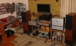
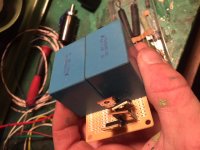
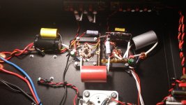
My GK71 (red color on the left) and GM70 (at the middle) are visible at this foto, I'll show the auto-bias arrangement, and yes, key parts for sound quality are good caps, I widely use 0,1uF silver-mica caps for shunting.
Attachments
Hmm again...looked at their site, didn't see mention of the auto bias...I did see them claiming 36WPC and "Pure Class A1". I won't even have at that...but Vladimir I would like to know what you are doing still, or rather see it,
Loren
KB2WYL
Loren
KB2WYL
Thanks so much, but the pic didn't come through....Seems like I always end up hitting "preview post" as sometimes mine don't go through the first time either....I'm curious because I've seen a few auto bias configurations, but not much with DHT's...
Thanks,
Loren
KB2WYL
Thanks,
Loren
KB2WYL
Thanks so much, but the pic didn't come through....Seems like I always end up hitting "preview post" as sometimes mine don't go through the first time either....I'm curious because I've seen a few auto bias configurations, but not much with DHT's...
Thanks,
Loren
KB2WYL
I'll be able to post something with schematics at the end of our local day (its a midday here at the moment).
ah ok theres the first pic. Very nice, you do clean work. I have just started working with Aluminum. Taking some welding classes, working towards completely self sufficient chassis construction. These ones are, completely fabricated by myself, but even upon completion will not be perfect for sure. Again, very nice.
Loren
Loren
Ok great, thank you. I said earlier in the thread already but I should say again for you, I've built HV amps, I've built neg bias amps, DHT amps, etc etc...But I've never built one with all the above ....neg bias, HV DHT, and IT coupled....I chose the D3a and also negative bias/input transformer on it because this amp is a bit of an experiment for me. It will allow me to slowly upgrade/modify with things like better interstage transformers and learn with my own ears just how much of a difference it makes. Also stated earlier in the thread, the output transformers, are made specifically for Parallel GM-70, so there was no point in trying to find some other huge triode. This amp isn't about super high power SE, but rather headroom and good control at moderate levels.
It's bedtime here but i will check back tomorrow morning, when it's night time for you.
Thanks again for sharing the schematic, I absolutely love learning about things I am not familiar with.
Loren
KB2WYL
It's bedtime here but i will check back tomorrow morning, when it's night time for you.
Thanks again for sharing the schematic, I absolutely love learning about things I am not familiar with.
Loren
KB2WYL
I'll be able to post something with schematics at the end of our local day (its a midday here at the moment).
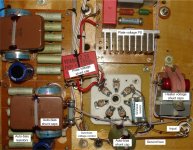
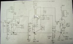
I post here the picture of GM70 socket with some wiring.
First I should mention, that the heater PS affects sound, therefore its output is shunted by caps close to GM70 heater pins (470uF Elna Cerafine, 2u2 polypropylene, 0,1uF silver-mica). Heater PS follows a spirit of that by Rod Coleman, but its current source is assembled on power jFets kp903a. The + of the heater PS is connected to the ground bus.
Plate voltage +950V is supplied via the transistor "virtual battery", and shunted by WIMA FKP 0,15uF 1250V just at the plate pin. This helps to avoide B+ variations under signal, what is good for bass notes reproduction.
Auto-bias voltage is formed by six 1K2 5W wirewound resistors (three in parallel, than each triplet in series). The cathode resistor value is 800 Ohms.
Tubes operate at "easy" mode, bias voltage close to 72V, current = 72/800 = 90mA. Tubes will serve for long period. The "resistor" is carefully shunted - 470uF Hitachi lytic, 20uF polypropylene, 0,82uF polystyrene, 0,1uF silver-mica.
Output trafo - 40cm2, turns ratio 50, 4 Ohms speakers (PMC EB1i). Output impedance of the amp is around 0,83 Ohms.
Input stage - EL803S Telefunken in penthode, driver stage - 6S4S DHT tube (300B would be even better). Volume pot - 10k DACT. Interconnect cables Analysis Plus Siulver Oval In 1,5m. Speaker cables (biwiring) - Stereovox 600 and 2x8mm2 to bass section. CD player Yamaha S2100.
Attachments
Ahh ok. I see, you were referring to cathode bias. Yes, I have seen plenty of that and it is certainly possible with the GM-70. I like your implimentation, good Job. If you look back in the thread you will see some preliminary schematics of mine, the one for the amp itself hasn't changed much. I am not doing cathode bias, but I am using cathode attenuation, through between 65-75ohms, to set a little voltage on the cathode in an attempt to balance gm of the tubes. as you know GM-70s vary a lot from tube to tube. We'll see how it works, but I am keen on keeping the negative supply for now. My bias supply is going to be very quiet hopefully, all passive and less than 1mv ripple.
We'll see...
I'll study yours a bit more this evening after work. thanks so much again,
Loren
KB2WYL
We'll see...
I'll study yours a bit more this evening after work. thanks so much again,
Loren
KB2WYL
Hi All
Just a quick update, on my way out the door. Last night finished last of boards that I had to design. Last is Rod's board, but that's almost like cheating with instructions hi hi. Tonight hopefully I can start doing layout and get some holes drilled. I want to finish these chassis.
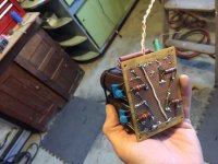
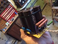
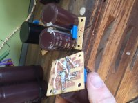
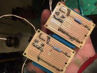
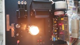
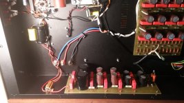
I've included pics of The Bias supply and the B+ and the DC heater for the D3a.
Also included pics of the main -120v Bias for the GM70, and the cap boards for the HV
The rest is figured out but a lot of it is just chokes that go on the chassis and are wired to these boards (like the D3a B+, looks like not much on board, but it's a choke input supply in an LCRCLC config.)
So yes, still long ways to go but most of the math is done for now at least.
I can't remember, how do I upload PSUD files? I tried changing the extension but then my computer changes the file to a jpeg and I can't open it and..grrrr...I have all 6 supplies all done in PSUD and I would love to upload them. By the time this thread is through it will be an instruction manual hi hi.
Thanks again,
Loren
KB2WYL
Just a quick update, on my way out the door. Last night finished last of boards that I had to design. Last is Rod's board, but that's almost like cheating with instructions hi hi. Tonight hopefully I can start doing layout and get some holes drilled. I want to finish these chassis.
I've included pics of The Bias supply and the B+ and the DC heater for the D3a.
Also included pics of the main -120v Bias for the GM70, and the cap boards for the HV
The rest is figured out but a lot of it is just chokes that go on the chassis and are wired to these boards (like the D3a B+, looks like not much on board, but it's a choke input supply in an LCRCLC config.)
So yes, still long ways to go but most of the math is done for now at least.
I can't remember, how do I upload PSUD files? I tried changing the extension but then my computer changes the file to a jpeg and I can't open it and..grrrr...I have all 6 supplies all done in PSUD and I would love to upload them. By the time this thread is through it will be an instruction manual hi hi.
Thanks again,
Loren
KB2WYL
Attachments
-
 gm70hv2.JPG77.5 KB · Views: 113
 -
 gm70hv.JPG113 KB · Views: 120
 -
 gm70bias2.JPG110.2 KB · Views: 127
 -
 gm70bias.JPG106.6 KB · Views: 126
 -
 d3aheater2.JPG110.1 KB · Views: 114
 -
 d3aheater.JPG119.1 KB · Views: 311
 -
 d3abias2.JPG103.1 KB · Views: 309
 -
 d3abias.JPG106.9 KB · Views: 347
 -
 d3ab+2.JPG136.3 KB · Views: 350
 -
 d3ab+.JPG99.5 KB · Views: 350
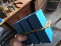
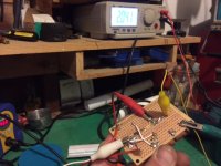
last boards
have been built now. Tomorrow is welding class up at the local community college, but hopefully Wed. night will be board placement to see how it all fits, then onto plywood full amp run. coming along...
Loren
KB2WYL
have been built now. Tomorrow is welding class up at the local community college, but hopefully Wed. night will be board placement to see how it all fits, then onto plywood full amp run. coming along...
Loren
KB2WYL
Attachments
Hi,
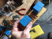
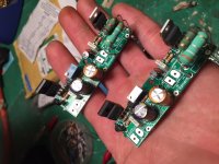
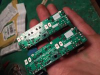
I've attached my GM-70 all DHT project pictures. I think that everything is self explanatory. PSU for B+ is CRCRCRCRC. Heaters are powered by modified SMPS, GM-70 and driver tubes also. Every tube has its own SMPS.
From my standpoint, chassis you are going to use is WAY TO SMALL for 4x GM-70 tubes, but you'll figure that out if you put 4 on that chassis 😎
What OPTs are you planning to use?
Regards
Attachments


Hi,
I've attached my GM-70 all DHT project pictures. I think that everything is self explanatory. PSU for B+ is CRCRCRCRC. Heaters are powered by modified SMPS, GM-70 and driver tubes also. Every tube has its own SMPS.
From my standpoint, chassis you are going to use is WAY TO SMALL for 4x GM-70 tubes, but you'll figure that out if you put 4 on that chassis 😎
What OPTs are you planning to use?
Regards
IMO, heaters could be powered by standard 24V SMPS, tuned to 25-26V, and the excessive 5-6V are to be lost at the intermediate (between the SMPS and the heater) CRCRCRCR. The last CR should be with sound quality C and R. I used this approach in gk71 project, and the heater voltage had near 0,1mV ripples peak-to-peak. Without CRCRCRCR one would have around 100mV ripples of heater voltage.
That's right!
I use the same approach. I've measured my amps with R&S Audio Analyzator to fine tune it and everything is as expected.
But, I'm not promoting my amp, I'm just sharing my experience and I can tell that chassis is too small for 4 pcs GM-70. Schematic can be modified later, but to change the chassis once everything is done is much more work ...
The Chassis would indeed be way too small for 4 GM-70. That's why these are monoblocks. Each chassis is 2 GM-70, so each chassis has only half of what you may be thinking. Also, All of the large iron is up top. The rest, under the hood, has a space that is over 4 1/2" deep by 14" x 23"....It is plenty of space. Thank you for your pictures, I appreciate it. I learned long ago, before I started playing with HV especially, to make sure everything fits on a chassis before you go ahead and design/build the amplifier.
Maybe I need to clarify...it all fits just fine, I am simply deciding upon the exact placement of each thing. I like my under-hood layouts to be very neat. During design and testing one always ends up changing a little, capacitor values etc, so I had to wait until all boards were built and tested before I did the final layout.
SMPS cxan work for the heaters yes, but I prefer Rod's boards. SMPS do not have a soft start, and a lot of filtration is needed to get out the rf hash. I am a ham radio operator and I try to stay away from switch mode power supplies altogether because of the cheap construction and the rf interference caused by them.
These heaters are Choke input supply, then onto Rod's boards, then onto the heaters. There is very little heat generated in the heater supply itself, compared to large dropping resistors.
You said 25V dropping down to 20V by the time it gets to the filament, that's 15 watts of heat just in the voltage dropping, and I am trying to keep heat under the hood down to a minimum for service life.
Thanks again for the comments and pictures. This has been a great thread so far.
Loren C.
KB2WYL
Also, Flikoman, I see you are using IT as well. Your schematic is nicely drawn, by the way. Which IT are you using, and have you tried any others (other IT's or other coupling schemes)? A ny positive/negative results?
Thanks,
Loren C.
KB2WYL
Thanks,
Loren C.
KB2WYL
2 GM-70 per chassis is much better 😉
Yes, with SMPS there is some more heat in the voltage dropping, but I can assure you there is no interference caused by them.
I like your project a lot, so I'm trying to help you out any way I can. I see that you know what you are doing, so, another 'set of eyes' won't be of any harm. 🙂
What did you said about OPTs? Where did you get them?
Regards
Also, Flikoman, I see you are using IT as well. Your schematic is nicely drawn, by the way. Which IT are you using, and have you tried any others (other IT's or other coupling schemes)? A ny positive/negative results?
Thanks,
Loren C.
KB2WYL
Yes, I try to draw it so everyone can read it. It's much easier that way.
IT is DIY. My colleague and dear friend Davorin (he is registered here also) has much more experience than me. He got ahold of some iron for chokes and he experiented with them and found out that they are great for IT's too.
Specification:
- (2 : 2) or (1+1 : 1+1), or (2 : 1+1), or (1+1 : 2), or (1 : 1), or (1+1+1 : 1), or (1 : 1+1+1)
- 10kOhm : 10kOhm connected as (2 : 2); 20Hz-20kHz +/-0,5dB with Idc=25mA
- Idc=30mA (max)
- Pmax=2W
- L > 200H with Idc=25mA with all sections in series (connected as choke)
- L > 54H:54H connected as 2 : 2
This is universal IT. I use it as 1:1. Sadly, I never tried another IT but measurements confirm this statement: " 20Hz-20kHz +/-0,5dB with Idc=25mA", so I'm very happy with it for now.
You are using Lundahl transformers?
My OPTs are Fiat transformers, dual C core with 0.1mm laminations, audio quality.
Regards
Yes I am using Lundahl. At least 70H when connected as I have it (2756 1:1) with up to 25ma (I'm using about 21ma).
That's for the driver IT, the input IT is amorphous core 1690, can't remember the specs off hand but it sounds very good, I think actually specs of this one are very close to yours, I think they both are, both of my IT's. I'll have to look but I'm almost positive -1db is 25hz with the 2756 and 20hz with the 1690.
Rest of iron is from Heathkit transmitter, and output transformer is a Dual C-core also. So we're very similar in these ways, except I'm only going 2 stages.
Thanks again,
Loren C.
KB2WYL
- Status
- Not open for further replies.
- Home
- Amplifiers
- Tubes / Valves
- Parallel GM70 Amp