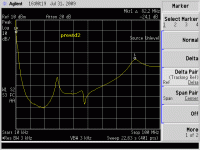
Me think me will ask me doctor for an earupgrade😱One more graph, here is the PSU Power Supply Suppression Ratio(PSSR) Near 60dB at 100Mhz
Me oldie ears cant hear 100Mhz or higher without a reciever😀
Me oldie ears cant hear 100Mhz or higher without a reciever😀
It is blocked anyway 🙂
Looks like its down 35dB at 1Ghz, allmost RF immune, impressing😉
That depends on the 10uF output capacitor (and other factors, like PCB).
If we examine the signal path construction of some competent RF function generator, awe at the work of the magician engineers and marvel at the heroic shielding and weird parts, then we know why we can't expect anything better than 70-80dB PSRR up to few decades of kHz beyond the audio band with typical construction.
If we examine the signal path construction of some competent RF function generator, awe at the work of the magician engineers and marvel at the heroic shielding and weird parts, then we know why we can't expect anything better than 70-80dB PSRR up to few decades of kHz beyond the audio band with typical construction.
That is so true 🙂
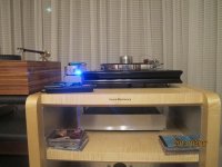
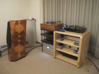
Well guys, i am loving it- R3 mate with Benz Ruby 3H-Turntable Once Analog(Aus made)/Basis Vector 3 arm. Compare to my previous phonostage Herron Audio(tube) the presentations is very different ie more laidback, no noise and so much more details😀
Very nice to hear! After we had so much trouble getting the parcel into your hands, in the end it turned out well...
That sounds good 🙂 be happy in ParadiseAny pictures to show?
Yeah, my rig:
Attachments
Very nice to hear! After we had so much trouble getting the parcel into your hands, in the end it turned out well...
Thank you for all your help Alfred. I just added a rotary switch for catridge loading as per build guide. Even more flexibility.
Quan
Thank you for all your help Alfred. I just added a rotary switch for catridge loading as per build guide. Even more flexibility.
Quan
your system looks great, I am sure it is more than appropriate to hear differences in phono stages!
A new solution for the drifting offset came up in the German Paradise Forum.
The offset drift ( typical plus-minus 25mV ) goes down to less then 5mV when the transistors are thermally coupled so it is a thermal drift problem.
Ones the Paradise is in a closed case it goes away. Another solution is to simply build a card bored box and slide it over the low level transistors.
That explains why the guys that have the Paradise encased did not experience that issue.
A new solution for the drifting offset came up in the German Paradise Forum.
The offset drift ( typical plus-minus 25mV ) goes down to less then 5mV when the transistors are thermally coupled so it is a thermal drift problem.
Ones the Paradise is in a closed case it goes away. Another solution is to simply build a card bored box and slide it over the low level transistors.
That explains why the guys that have the Paradise encased did not experience that issue.
We allready had some hints from diyaudio in this respect.... So it is confirmed.
maybe these transistors can be glued together with pottting compound which has a very low thermal resistance before soldering them on to the board ? (not sure how far these items are apart)
- Home
- Source & Line
- Analogue Source
- Paradise Builders