Energize the main voltage source for ACampl=1, also the load sink. Run an AC sweep on the output with the probe off .params prb=0 go click to the chart's left side and ask for logarithmic. What you see complies to Ohm scale too now. That way you can see what it does across wide band.
Tonight, first there is work to do 🙂
Hi, recently received a v2 set of boards and bits. The build doc is for v3. Is there anything I should be aware of? Thanks in advance, Bill
Also will this ps work for this build?
http://www.extech.com/instruments/product.asp?catid=39&prodid=210
Also will this ps work for this build?
http://www.extech.com/instruments/product.asp?catid=39&prodid=210
Last edited:
hi berndt,
yes the R2 pcb's really are R3, my mistake i forgot to fix the version number when i ordered the pcbs. so the documentation is alright.
you will need two of these power supplies for the paradise, as positive and negative supply voltages are needed.
happy building!
yes the R2 pcb's really are R3, my mistake i forgot to fix the version number when i ordered the pcbs. so the documentation is alright.
you will need two of these power supplies for the paradise, as positive and negative supply voltages are needed.
happy building!
With a load of 50mA(dc) and 50mA(acpp) sinusoidal load variance (eg a load sinus of mA to 25mA(low) to 75mA(high)) the simulator gives a 31uVpp ripple. That should be equivalent to (in my reckoning) 31upp/50mpp = 620uOhm. But this is for a very unrealistic load (really worst case 🙂). If this is what you wanted to know 🙂
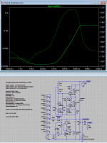
Here is the PSU impedance plot:
Iccs=150mA
Iload=70mAdc+50mAacpp
Imp(min)=652uOhm, Imp(max)=106mOhm
Phase(max)=86deg.
The slight rise in output impedance, from 100mHz to 10Hz, could have been avoided by replacing the 680 Ohm(rb) resistor with a current source, but where is a 1mA 500mV ccs? (I see now how I could have done this using another opamp, but how complex can/may/should it be 🙂). The shown ccs is set for 0mA (I should have removed it for clarity).
Attachments
Last edited:
The take off is rather steep above 1kHz but anyway I can try sim it with my model library too at a point and see how it plots if any different with methods also. Beyond theory of its operation, more good news is that the PSU with the Toshibas is stable under all signal types running in the phono, I tested it for that earlier today. During that process I stumbled on a worrying find nonetheless. I was using Arta's sig gen with an EMU Tracker via 1:200 1K-5 Ohm divider for low noise 0.5mV amplitude various signals and I fed it pink noise at a point. Well, with that signal it goes bananas. The PSU is stable but the main circuit outputs this:
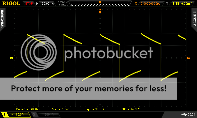
6.5-7Hz square-ish with very high DC content. Its with the scope AC coupled in the picture. Looks like its the servo? The only difference to regular BOM is I have 10K injections instead of 150K. Can you repeat that in your build? In mine it repeats 100% every time.
6.5-7Hz square-ish with very high DC content. Its with the scope AC coupled in the picture. Looks like its the servo? The only difference to regular BOM is I have 10K injections instead of 150K. Can you repeat that in your build? In mine it repeats 100% every time.
could it be a ground loop? I had a similar issue with my sound card, but only with one channel, strangely enough. same problem when I feed the output of the sound card straight back into the sound card, even without signal. It is enough when the ground leads are touching, oscillation started. It may or may not be the same issue though.... my paradise measurements revealed no such issue....
I tried that both when looping and with just feeding input and only watching it on the scope for output. First hint was when I saw the clip led on the card blinking while trying signals. After it does it latches if I won't disconnect the output. Will investigate again today. I think it may be so for IMD multi-tone too. Will try other software also, and the ground lift switches on the EMU.
I guess this one is for the development team. Did you ever try any other kind of transistor for the amp part during the development, like 2sa970/2sc2240 and similar?🙂
I guess this one is for the development team. Did you ever try any other kind of transistor for the amp part during the development, like 2sa970/2sc2240 and similar?🙂
Actualy I did, and in the 'power-amp-internal-PSU'-version of the shunt (that I am using, here the PSU input voltage is 70V) I am using 2sa970/2sc2240's. For as far as I know, no problems there.
could it be a ground loop? I had a similar issue with my sound card, but only with one channel, strangely enough.
I experimented more today and I found it has to do both with how it sees the card's ground plus having signal content near DC. Multitone and PNPink (periodic noise form) excites it the most and if there is no GND lift it goes over the top. Single tone for THD is OK, two tone for IMD is OK, white is OK. Don't know about disc eccentricity and rumble if it can unsettle it until ready for hook up, I hope not. Showed 0.0015% for 0dBV=1VRMS in 1kHz test. Its 1/f till 20Hz is at -98dBV and its hiss completely follows Riaa EQ HF demise only if ground lifted to the signal source, else it flattens above 1/f. Hum was at -80dB but its in open air now so its only indicative. The 2SC5171/2SA1930 PSU did not present difficulties still. From just eyeballing the curve with octave smoothing it looks a bit treble oriented and bit high around 1kHz just like the early gen & scope spot test have indicated but I will have to listen to it before any tweaks there. Having to complete the half baked next channel now I guess. Luckily the EMU tracker pre proved well protected to the various overloads and DC peaks during those push tests.
Don't know, that one question is for the designers. I will use less lytics value in the entrance stage to stay on the safe side as a general precaution in my build for one.
Don't know, that one question is for the designers. I will use less lytics value in the entrance stage to stay on the safe side as a general precaution in my build for one.
This was mentioned before by Joachim as the value from the design stage was at that time dubled.
Yes, the emitter decoupling caps have a huge size. We had a discussion before.
One guy preferred the sound with a smaller value.
We also talked about " forming".
They need several days to settle to a low leakage current.
One guy preferred the sound with a smaller value.
We also talked about " forming".
They need several days to settle to a low leakage current.
I leave the one I am going to use connected for a couple of days to a small PSU
A simple LM 317 set for the capacitor nominal voltage is enough for this purpose.
It may be to early to ask but could the component changes became official and be added to the build guide?
I can see no problems whatsoever for a change on the existing (running) builds as the PCB are really good and can take quite a lot of abuse
Last edited:
Don't know, that one question is for the designers. I will use less lytics value in the entrance stage to stay on the safe side as a general precaution in my build for one.
Let us know what final values you choose as these affect response. I am designing a riaa calculator for the paradise and your input will surely help a lot.
I experimented more today and I found it has to do both with how it sees the card's ground plus having signal content near DC. Multitone and PNPink (periodic noise form) excites it the most and if there is no GND lift it goes over the top. Single tone for THD is OK, two tone for IMD is OK, white is OK. Don't know about disc eccentricity and rumble if it can unsettle it until ready for hook up, I hope not.
Many thanks for this comprehensive analysis. Should there be a potential instability between incoming LF signals, the servo, and the input stage behaviour at low frequencies? Interesting question.....
I can only add that I built the paradise as described, and in all my listening, and a friendss listening, LF has never come up as a problem. I also have not from any other builder about this, so it seems we are reasonably safe from stuff injected by the turntable. But it may well be that none of us has a DC-coupled system....
- Home
- Source & Line
- Analogue Source
- Paradise Builders