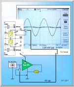
AC modulation at C8
To have a look at the ac modulation across C8 . . .
Gave 4V (peak2peak) of 50Hz signal into the input, and got 120mV (peak2peak) across C8. The phase shift was about 90deg. This ac modulation would go back to the input through the dc voltage divider and might craete 2nd harmonic distortion.
The ac modulation was getting lower at higher frequencies.
It was an intersting measurement 🙂
Attachments
Zen Mod said:hehe
playin' with sin bin ........... 😉

Is Papa angry with me because I captured part of his drawing without permission?
Zen Mod said:that other thread
I got "back-off", LOL . . .
Will see what kind of interest will happen there, LOL . . .
Thanks, God, I didn't make Papa angry 🙂
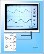
Babowana said:100Hz ripple before and after the 0.93mH air coil
I don't know why there is a nipple on the top of the ripple (before the coil).

because
choke
take
and
give
energy
you
can
imagine
it
as
one
wild
spring
wandering.......
I said that I would no more call you Papa. But, the title of the
thread . . . Ang ang ang . . .
Papa,
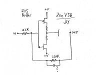
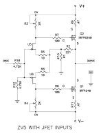
I'm going to apply the front part of F4 for my ZV5.
I will call it, Zen V5B ~ ^^
This is not all of a sudden, but actually I have thought about
the input buffer to ZV5.
Please watch my posts coming, and if I do stupid things,
kindly beat me. Thanks.
Attachments
I have repeatedly read the article of F4 with great and great interest.
I feel as if the sound of F4 were now whirling around my head.
Jealously thinking about Papa, who sees through all details in one look . . .
Sh@t! Why I have no such ability . . . ?
BTW, I have a small concern which is about the somewhat low sound
pressure of my J-low speakers for me to have F4. And, I’m still in love
with the sound coming out of ZV5 mono blocks.
Waiting in queue my turn to the bank counter, I was pondering, and
opened the pen and made a sketch. I’m going to try this.
It could appear that I made this in imperfection. But, what . . . ?
Just go ahead and see ~ ^^
Attachments
~ ^^
Thank you very much for the sweet rain, Papa.
I will follow your suggestion with deep appreciation.
I will walk around the whole land of Great China to find the jfets.
If not enuf, I will cross the lands over the sea.
My sodering iron is getting hot.
~ ^^
Thank you very much for the sweet rain, Papa.
I will follow your suggestion with deep appreciation.
I will walk around the whole land of Great China to find the jfets.
If not enuf, I will cross the lands over the sea.
My sodering iron is getting hot.
~ ^^
Luckily, I could order 100 pcs of Toshiba 2SJ108 today -- expensive.
Why 100 pcs? Hmm . . . some of them are for Choky, if he is ready
to pay his house ~ .^^.
But, I failed to get 2SK370.
I beg Papa for few? No . . . I'm not that thick face.
Yes! I remember that I have leftover of J310 behind the cascoded
SOBOZ (its nick name was Krazy) I built. Yes, number of the
leftover is more than 10 pcs. Let me use them.
By the way, J310 useful . . .?
The max Vds rating of J310 is 25V while the +Vrail of my ZV5 is
about 20V. And, about 4V is deducted from it, so the actual Vds is
around 16V. It is a problem . . . ? No, I don't think so!
Okay, I will go ahead with the input complentary pair of J310/2SJ108
until I get 2SK370. Why not . . . ? This is not strange more than I
am already using the odd power mosfet pair of
IRFP9240/IRFP250N.
These pairs might be really strange to many of hi-end audio fans.
But, it does not matter. . . kh kh kh . . .
Attachments
Keep in mind that you'll be adjusting those potentiometers over
a period of time while the amp warms up. If it has a cover,
you will want that cover on during warm up. If the bias drift
is not stable enough (usually not enough sinking) then thermistors
in parallel with the pots will help.
Nevertheless, you will probably like the sound.
😎
a period of time while the amp warms up. If it has a cover,
you will want that cover on during warm up. If the bias drift
is not stable enough (usually not enough sinking) then thermistors
in parallel with the pots will help.
Nevertheless, you will probably like the sound.
😎
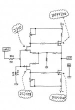
babo
you can try fiddling with just one pot-scheme as in Oly's little amp ;
that will have influence on degeneration and overall A ,but-who knows,maybe that will suits you;
as WR you can use 1K and series it with,say,22 ohms
EDIT:
now I see that connection of feedback with my proposed concept will be questionable ,so just disregard my proposal;
anyway-if you matche few jfets you can also try that schmtc ,and tell us which you like more;
in any case ,do not use less than 2A through outputs .
Attachments
Zen Mod said:babo
you can try fiddling with just one pot-scheme as in Oly's little amp ;
that will have influence on degeneration and overall A ,but-who knows,maybe that will suits you;
as WR you can use 1K and series it with,say,22 ohms
EDIT:
now I see that connection of feedback with my proposed concept will be questionable ,so just disregard my proposal;
anyway-if you matche few jfets you can also try that schmtc ,and tell us which you like more;
in any case ,do not use less than 2A through outputs .
As I informed you earlier, I had built an amp with the dual jfets,
2sk389 and 2sj109 (a complementary differential input).
My sister is still using the amp. Luckily, she is still happy with.
For the time being, it seems to be difficult for me to get the jfets.
I will keep the drawing, and when I have chance . . . You know . . .
Thanks,
Nelson Pass said:Keep in mind that you'll be adjusting those potentiometers over
a period of time while the amp warms up. If it has a cover,
you will want that cover on during warm up. If the bias drift
is not stable enough (usually not enough sinking) then thermistors
in parallel with the pots will help.
Nevertheless, you will probably like the sound.
😎
Thanks, Papa!
I'm more than happy with your advice and encouragement.
No wire cutting yet, but I'm excited with the sound on the drwg.
I feel tommorrow is a long time, waiting the arrival of 2SJ108.
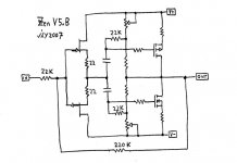
I'm not the same as you. I always need time in understanding of
what is happening in the samll circuit world. Moreove, if I have no
anchor, my thinking floats free with no direction. Therefore, I
have made another drawing, wishing that the circuit would
sense my thinking and open the door to its world.
With ZV5, I spent three hours of the night time in adjustment of
bias, and three nights. In addition, I was monitoring the drift
from time to time. It's fun. I'm a DIYer. I will do my best to
utilize the thermistors properly .^^.
And, I'm ready to try even paralled jfets in case . . . .^^.
Attachments
Babowana said:
Thanks, Papa!
I'm more than happy with your advice and encouragement.
No wire cutting yet, but I'm excited with the sound on the drwg.
I feel tommorrow is a long time, waiting the arrival of 2SJ108.
I'm not the same as you. I always need time in understanding of
what is happening in the samll circuit world. Moreove, if I have no
anchor, my thinking floats free with no direction. Therefore, I
have made another drawing, wishing that the circuit would
sense my thinking and open the door to its world.
With ZV5, I spent three hours of the night time in adjustment of
bias, and three nights. In addition, I was monitoring the drift
from time to time. It's fun. I'm a DIYer. I will do my best to
utilize the thermistors properly .^^.
And, I'm ready to try even paralled jfets in case . . . .^^.
try with thermistors in parallel with multiturns,not in series
Zen Mod said:try with thermistors in parallel with multiturns,not in series
It seems that I'm going wrong.
By the way, what are the multiturns? I only know the difference
between sigle and multi turn of the adjusting screw.
Do you mean that I should put each themistor between the V rail
and the drain?
Thanks,
Babowana said:
It seems that I'm going wrong.
By the way, what are the multiturns? I only know the difference
between sigle and multi turn of the adjusting screw.
Do you mean that I should put each themistor between the V rail
and the drain?
Thanks,
multiturn trimpot;
do not place termistor in series with trimpot,place it in parallel
- Status
- Not open for further replies.
- Home
- Amplifiers
- Pass Labs
- Papa! I want to have Zen V5.