zenlite zen lite zen-lite zenv5 zen v5 zen-v5
congrats babo!
🙂
in my lineup mind
😎 Zen V5 RULES 😎
... when it comes to ultimate designs I have encountered in this forum
... too bad I did not come up with ZenV5 circuit before Nelson Pass
... it would have been something to accomplish in life
Same thing with Zen Lite 🙂
... why did noone else come up with that trick!
lineup
- thinks some nelson's stuff is not over the edge interesting
- but some of it Really Hit's The bullseye
Babowana said:
After all wire arrangement, tested the sound,
got wonderful sound,
and wanted to finish this project,
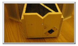
completing the housing of the PSU body.
congrats babo!
🙂
in my lineup mind
😎 Zen V5 RULES 😎
... when it comes to ultimate designs I have encountered in this forum
... too bad I did not come up with ZenV5 circuit before Nelson Pass
... it would have been something to accomplish in life
Same thing with Zen Lite 🙂
... why did noone else come up with that trick!
lineup
- thinks some nelson's stuff is not over the edge interesting
- but some of it Really Hit's The
bullseyeRe: zenlite zen lite zen-lite zenv5 zen v5 zen-v5

Thanks, Lineup.
I get deeper meanings from ZV5. It's great, isn't it 🙂
Choky said:box I can use for parts storage ..........
lineup said:congrats babo!
🙂
Thanks, Lineup.
I get deeper meanings from ZV5. It's great, isn't it 🙂
Zen Mod said:. . . in that case wires can be shorter . . .
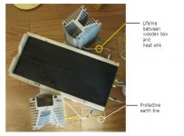
Actually, there is a detachable lifeline formed by five wires
between the heat sink and the wooden box - this was my
real concern.
Five wires are:
1 input wire to the gain mosfet gate
2 output wire from the gain mosfet drain
3 preregulated wire to the regulator mosfet drain
4 reference voltage wire to the regulator mosfet gate
5 regulated voltage wire from the regulator source
And, these five are tightly braided together forming the lifeline
(about 20 cm length).
So, I was worrying about unwanted high frequency oscillations
which could be possible due to the following causes:
1 capacitive and magnetic coupling from the output to the input
2 load lead inductance feedback from the power line to the circuit
My worrying was just a worrying, with luck of no such oscillation 🙂
By the way, the five wires should have been six including one
more wire, which should have been a protective earth line from
the heat sink to the protective earth point. But, my ill plan forgot
it. Therefore, I am using a separated wire having snakehead clip
at each end. One head is biting the heat sink while the other
biting the protective earth point.
Any comment or advice? Tks
Attachments
Babowana said:
Actually, there is a detachable lifeline formed by five wires
between the heat sink and the wooden box - this was my
real concern.
Five wires are:
1 input wire to the gain mosfet gate
2 output wire from the gain mosfet drain
3 preregulated wire to the regulator mosfet drain
4 reference voltage wire to the regulator mosfet gate
5 regulated voltage wire from the regulator source
And, these five are tightly braided together forming the lifeline
(about 20 cm length).
So, I was worrying about unwanted high frequency oscillations
which could be possible due to the following causes:
1 capacitive and magnetic coupling from the output to the input
2 load lead inductance feedback from the power line to the circuit
My worrying was just a worrying, with luck of no such oscillation 🙂
By the way, the five wires should have been six including one
more wire, which should have been a protective earth line from
the heat sink to the protective earth point. But, my ill plan forgot
it. Therefore, I am using a separated wire having snakehead clip
at each end. One head is biting the heat sink while the other
biting the protective earth point.
Any comment or advice? Tks
you know that I'm always full of-with advices
just make whole mess as I draw , make holes ditto between heatsinks and box,put wires already soldered to mosfets on sinks through holes and solder inside.
htsnks can be grounded on screw heads inside of box.
biggest work must be dislocating of in-out connectors from present back to present top plate
anyway- your decision is final

Confirmation of input impedance
I have assumed that R1 is considered as the input impedance
if I assume the node just behind R1 as a virtual ground.
I have R1 of 500 (1K//1K).
I measured the input impedance of about 500.
I think my assumption was reasonable. Right?
I have assumed that R1 is considered as the input impedance
if I assume the node just behind R1 as a virtual ground.
I have R1 of 500 (1K//1K).
I measured the input impedance of about 500.
I think my assumption was reasonable. Right?
Attachments
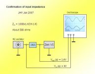
seems all right
usuall way of measuring this is to use pot instead 1k ,and when you have same voltages across pot and input of stage , you can measure exact res of pot and then you know input resistance.
anyway,both ways are equally good
buda is in everything 😉
usuall way of measuring this is to use pot instead 1k ,and when you have same voltages across pot and input of stage , you can measure exact res of pot and then you know input resistance.
anyway,both ways are equally good
buda is in everything 😉
Babowana said:Choky
I'm still on the spammer list till this time.
😕
me to 😕
use my gmail account......I wrote addy already,but to save you from search.............sasica5ATgmail.com
Zen Mod said:usuall way of measuring this is to use pot instead 1k
Why I didn't think about it?
Thanks, Choky, from a babo.
It is a great fun in confirming my assumption
one by one. I learn and get self-confidence.
🙂
Surprise, surprise
Any one built or building Zen V5?
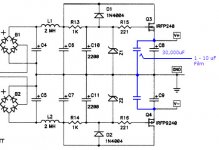
Please spend some $ to bypass the big electrolytic caps, C8 and C9 with 1 - 10 uF film unless you are using high quality of C8 and C9. It will very much improve the frequency response around top-end.
I am using Solen 4.7 uF, and get natural details of cymbals' delicate top-end sound.
If you don't agree with the result, I have intention to compensate your expense invested for the film caps 🙂
Sorry, Nelson, for copying your drawing without getting any permission
Any one built or building Zen V5?
Please spend some $ to bypass the big electrolytic caps, C8 and C9 with 1 - 10 uF film unless you are using high quality of C8 and C9. It will very much improve the frequency response around top-end.
I am using Solen 4.7 uF, and get natural details of cymbals' delicate top-end sound.
If you don't agree with the result, I have intention to compensate your expense invested for the film caps 🙂
Sorry, Nelson, for copying your drawing without getting any permission
Attachments
Walking-distance away from my place, we have two cinemas: Cinema A and B.
I often go to Cinema A whenever they play English-speaking movies, and enjoy both the big screen and the movie sound. This Cinema A seems to be using horn speakers. I hear the typical coloration of the horn speakers and somewhat hardness.
Last night, our apartment was under the blackout – no electricity. It was dark and cold so that I walked down the stair ways and went out. And, I found myself standing at the ticket widow of Cinema B playing The Guardian. But, the price was 14% more expensive compared with Cinema A for the same movie. I wondered reason why. Probably, the screen bigger, or the seat more comfortable, or the movie sound system better. Wow, actually the sound was much better. Keeping energy, the sound was smoother and warmer. The helicopter propellers were roaring realistic.
For me, the improved sound was worth the 14% higher price (ticket of about USD 10.5).
Audio-diyers’ ears are sharp! 😎
Babowana said:Walking-distance away from my place, we have two cinemas: Cinema A and B.
I often go to Cinema A whenever they play English-speaking movies, and enjoy both the big screen and the movie sound. This Cinema A seems to be using horn speakers. I hear the typical coloration of the horn speakers and somewhat hardness.
Last night, our apartment was under the blackout – no electricity. It was dark and cold so that I walked down the stair ways and went out. And, I found myself standing at the ticket widow of Cinema B playing The Guardian. But, the price was 14% more expensive compared with Cinema A for the same movie. I wondered reason why. Probably, the screen bigger, or the seat more comfortable, or the movie sound system better. Wow, actually the sound was much better. Keeping energy, the sound was smoother and warmer. The helicopter propellers were roaring realistic.
For me, the improved sound was worth the 14% higher price (ticket of about USD 10.5).
Audio-diyers’ ears are sharp! 😎

those must be bad horns in cinema A
ya almost tell
horns=bad


Vix said:Btw, what did you drink?😀
One bottle of alcohol-free beer
and another bottle of non-alcohol beer 😀
Babowana said:
One bottle of alcohol-free beer
and another bottle of non-alcohol beer 😀
Bad!
 😀
😀Bad, bad, bad . . .
Something seems to be going stange with me.
What is wrong with me?
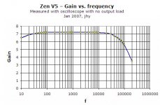
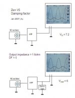
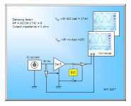
Last time I measured the damping factor of 5.
But, when I measured it again, I got 8.
Why measured again?
Because last time I measured it at too high frequency.
So, I wanted re-measurement at 50Hz.
On 50Hz signal
DF = 8 (8 ohm load)
Output impedance = 1 ohm
The original article says, DF of 4 . . .
Where I am wrong?
These days I am having too little sleep . . .
Something seems to be going stange with me.
What is wrong with me?
Last time I measured the damping factor of 5.
But, when I measured it again, I got 8.
Why measured again?
Because last time I measured it at too high frequency.
So, I wanted re-measurement at 50Hz.
On 50Hz signal
DF = 8 (8 ohm load)
Output impedance = 1 ohm
The original article says, DF of 4 . . .
Where I am wrong?
These days I am having too little sleep . . .
Attachments
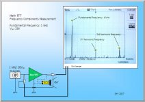
Math FFT frequency component (spectrum) measurement
Okay, I took this measurement.
Not to get the distortion figures, but just to have a look.
Why . . . ? Of course, for fun.
The fundamental frequency was 1 kHz of 20V(peaktopeak)
at the output to the 8 ohm load (about 6W). From this test,
my ZV5 shows both 2nd and 3rd harmonics. I guess that
if the power is varying, the portions of the 2nd and 3rd
harmonics would be also various.
If you find out any mistake in my measurement set-up,
I would much appreciate your comment.
🙂
Attachments
- Status
- Not open for further replies.
- Home
- Amplifiers
- Pass Labs
- Papa! I want to have Zen V5.