Babowana said:
...............
And, had another measurement -- clipping point. The symmetric clipping was starting from the point of about 34V pk-pk output ^^.

I bet that's loud enough for your spks 😉
Zen Mod said:I bet that's loud enough for your spks 😉
Yeah . . . loud enough.
In general, I kick the aass high up during weekend.
But, never at the top.
I want to respect my Japanese neighbours ^^~
~oo~
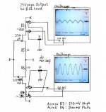
At amp's work with 25V pk-pk output to the 8 ohm load, I
measured differential ac voltage swing at R3 and R4. Actually, R3
and R4 are trimming pots. But, I roughly calculated adjusted and
fixed values as R3 of about 260 ohms and R4 of about 380 ohms.
Measurement results are 520mV pk-pk at R3 and 2000mV pk-pk
at R4. This means that R3 has less ac voltage swing than R4. If I
calculate these voltages to swinging current, R3 has 2mA pk-pk
hile R4 has 5.3mA pk-pk.
Interesting!
Due to these unbalanced ac current swings between R3 and R4,
the complementary power fets also amplify different ac currents.
As a result, the upper p-ch fet works like an Aleph CCS -- i.e. as
an active current source! And, the lower n-ch fet works like a
single ended amplifier.
Really, an intersting finding. I hope I am correctly understanding
the reason why it works like this babo ^^. But, a good sounding
babo ^^.
Attachments
Babo-
Not sure if you posted this somewhere, but I could not find it--what is the dc voltage on the gates of the jfets?
Also--what are voltages at sources of jfets?
I have been looking at your postings trying figure out exactly how that circuit works.
Also--I am looking at BOSOZ with jfets (2n4416) operating above IDSS to see how what happens.
JJ
jupiterjune said:Not sure if you posted this somewhere, but I could not find it--what is the dc voltage on the gates of the jfets?
Also--what are voltages at sources of jfets?
Zero volt at the gates. And, see post #217.
OK-
It just looked suspicious that the J310 had lower gain than the 2SJ108GR.
I thought the 2SJ108GR might be reverse biased, but I guess not.
I could not find a spec sheet for the 2sj108GR--what is the Gfs listed for it?
I found spec sheets for the j310 -- it listed Gfs as 8 minimum.
JJ
It just looked suspicious that the J310 had lower gain than the 2SJ108GR.
I thought the 2SJ108GR might be reverse biased, but I guess not.
I could not find a spec sheet for the 2sj108GR--what is the Gfs listed for it?
I found spec sheets for the j310 -- it listed Gfs as 8 minimum.
JJ
oops--
I meant to say "I thought the gate of the 2sj108GR might be forward biased..."
I thought the 2SJ108GR might be reverse biased, but I guess not
I meant to say "I thought the gate of the 2sj108GR might be forward biased..."
jupiterjune said:I could not find a spec sheet for the 2sj108GR--what is the Gfs listed for it?
I found spec sheets for the j310 -- it listed Gfs as 8 minimum.
There is no separate datasheet for 2SJ108GR.
The datasheet of 2SJ108 covers all.
2SJ108GR has Yfs (Gfs) as 8 min and 22 typical.
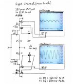
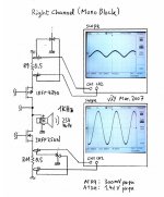
Babowana said:Here is another measurement from R-ch block.
The current swing at R9 is 0.6A pk-pk
while the swing at R11 is 2.82A pk-pk.
So, my Babo Zen is working similar as SE.
Steen, are you ready to drop ya jaw down to ya foot?
😀
you made Aleph

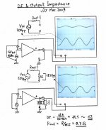
This will be my last post about the characters of the amp.
I find damping factor about 12 with 8 ohm load.
Output impedance is about 0.7 ohms.
Through this project, it seems that I have learned many things.
I am really pleased not only with the excellent sound, but also
for the good lesson about JFETs. Now, I have quite reasonable
self-confidence for the future application of them ^^.
Thanks, to all guys who have kept interests in the progress of
this project. And, special thank you, Papa . . . ^^.
Attachments

Don't mention tks.
Smoke not too much ^^.
The bent legs are due to the tests I had.
Any one is found wrong, I will re-send free ^^.
Enjoy!
Smoke not too much ^^.
The bent legs are due to the tests I had.
Any one is found wrong, I will re-send free ^^.
Enjoy!
~oo~
Before I leave this thread alone, few more things . . .
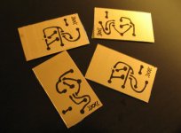
I replaced the two breadboards pictured in post #189 with my own PCB. My own PCB? Yes, my first try after my birth to this beutiful world. Last time, when I was measuring the oscilloscope responses, once I mishandled the probes and saw some of smoke from one of these beadboards. After the probes having been removed, I found that the amp was still working normal. But, I felt as if I were keeping the aching tooth. This was why I wanted to replace them with new boards and new components--but this time with diy PCB.
I cut the copper-clad board to the sizes, using the snap-off blade knife. On the copper side, I made the drawing of black wires with oil pen. Art work? No, not really. This was just a baby who stood up for the fist time. ^^
Before I leave this thread alone, few more things . . .
I replaced the two breadboards pictured in post #189 with my own PCB. My own PCB? Yes, my first try after my birth to this beutiful world. Last time, when I was measuring the oscilloscope responses, once I mishandled the probes and saw some of smoke from one of these beadboards. After the probes having been removed, I found that the amp was still working normal. But, I felt as if I were keeping the aching tooth. This was why I wanted to replace them with new boards and new components--but this time with diy PCB.
I cut the copper-clad board to the sizes, using the snap-off blade knife. On the copper side, I made the drawing of black wires with oil pen. Art work? No, not really. This was just a baby who stood up for the fist time. ^^
Attachments
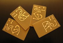
And, I put the boards into a plastic bowl with some of white cristals of Ammonium Persulfate, then added warm water of about 6-fold amount of Ammonium Persulfate. About fifteen mins. later, I put the boards out of the bowl and washed off them clean. It seemed that I kept the boards in the bowl too long. I found that the left copper layer was looking thinner than I expected.
Attachments
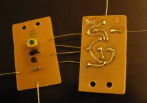
Hmm . . . the copper layer looked really thin so that I applied solders on it all the way before I made the 1mm through-holes. Then, I inserted components through the holes and soldered them all. Done! It was so easy. It took less than three hours for all.
By the way, This time, I picked up two "smaller" 2SJ108GRs having Idss of merely 5.45mA. Sure of 5.45mA? Sure. Nevetheless, the amp returned back to the same work as previous. No joke! WoaHahahahahaha . . . ^^
By the way, This time, I picked up two "smaller" 2SJ108GRs having Idss of merely 5.45mA. Sure of 5.45mA? Sure. Nevetheless, the amp returned back to the same work as previous. No joke! WoaHahahahahaha . . . ^^
Attachments
This thread has been quiet for some time, but would it be possible to sub a 2SJ74 (N ch) for the J310 and a 2SK170 (P ch) for the 2SJ108 in this circuit??
john65b said:This thread has been quiet for some time, but would it be possible to sub a 2SJ74 (N ch) for the J310 and a 2SK170 (P ch) for the 2SJ108 in this circuit??
Sure. Actually, the combo of 2SJ74/2SK170 is the better answer.
My latest V5 has 2SJ74 and 2SK170.
I had to use J310/2SJ108 as I could not get 2SJ74/2SK170 that time 🙂
- Status
- Not open for further replies.
- Home
- Amplifiers
- Pass Labs
- Papa! I want to have Zen V5.