Hi Prasi. What is this?
Ok I see,isn't good ,Vbe mult.must be in thermal contact with the VAS not with the outputs.
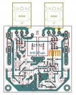
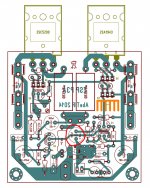
ESP P3A Layout
And the layout is here
ESP P3A Layout
Last edited:
Dears,
Any B & W , jpg or pdf files for direct printing
I've saved the plans for Mihai's layout (and some others), with PDF files also. Can send you by email.
(No, I haven't got the original layout by ESP, although being a very easy task to redraw it from pictures along the internet).
Gents please dont screw up my thread
This thread is to disscuss P3A properties qualities and considerations with comparison or not to other existing amplifiers, not to find a non recommended pcb for free ....
Thank you
This thread is to disscuss P3A properties qualities and considerations with comparison or not to other existing amplifiers, not to find a non recommended pcb for free ....
Thank you
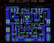
P3A, the most copied amplifier.
Not much new from Rod Elliot's work publihed in ESP, long ago. Still up to date.
Elliott Sound Products - The Audio Pages (Main Index)
All, that is worthwhile in audio design is in there.
Not much new from Rod Elliot's work publihed in ESP, long ago. Still up to date.
Elliott Sound Products - The Audio Pages (Main Index)
All, that is worthwhile in audio design is in there.
My apologies for posting it in wrong thread.
My intention was to choose the best and fine tuned design.
Regards,
Edison.
My intention was to choose the best and fine tuned design.
Regards,
Edison.
Hello,
I just built p3a with abetir pcb layout.
Feeding with bipolar 28vdc.
Powered up with dbt. Few seconds after 560ohm resistor smoked.. Small signal transistors bc546, drivers bc139&140 outputs a1492&c3856.
Any idea anyone?
ps: 2240 > 546 pinouts are arranged already. No diodes installed yet, including led..
Attachments
Sorry you are having a problem but its not a complex design and possible faults aren't particularly hard to diagnose. Let's think about the DBT first.
If you used a dim bulb tester, it would need to be fitted in the mains supply before the power supply and probably no more than about 40W bulb rating to protect anything. Does the bulb glow or flicker at all when you power up? If not, it can't be protecting your amp. and for the type of failure you have, it may not be helping. What sort of power supply are you using? Is it intended for permanent use with the amplifier or is it a dual bench supply that is suitable for high currents?
The only 560R resistor I can read on the layout diagram, is a dropping resistor between the -ve power rail and current source transistor Q3. This is in the input stage which should operate at very low (only 1-2 mA or so) current. If this stage draws enough current to burn the resistor, you have either made a mistake fitting Q1,2,3 or perhaps one is shorted or they are not genuine 2SC2240 transistors. Remove and test for shorts before refitting or replacing them as you don't need a repeat performance.
However, as you haven't fitted the LED yet, Q3 is not regulating anything and this could be the real problem. The LED is not an indicator but it is used as a voltage reference to maintain the small current. Don't omit it.
BTW, there are now plenty of fakes and poor copies of these obsolete parts so I wouldn't buy them. KSC1845/KSC992 are still in production and are drop-in relacements but there are plenty of other low noise transistors that will work fine here including the original specified ones.
Last edited:
No diodes installed yet, including led..
From ESP site, about the LED:
"This is not for appearance (although the green LED looks pretty neat on the board), but for the voltage drop."
Thank you guys..
This means, I have to read full explanation before act and do silly things.
Cheers,
Sb.
This means, I have to read full explanation before act and do silly things.
Cheers,
Sb.
Hello desert,
Sorry but it's really a bad design.
Grounding needs lot of improvement.
Regards
Prasi
Sorry but it's really a bad design.
Grounding needs lot of improvement.
Regards
Prasi
A couple other observations:
The LTP should be oriented so that they can be thermally coupled.
Same issue with the Vbe bias servo and driver
The LTP should be oriented so that they can be thermally coupled.
Same issue with the Vbe bias servo and driver
I ran a simulation with D1 disconnected. It shows dissipation in the 560Ω R7 resistor at 1.5W.
I thought so and you've proved it: good job Brian!
Jacques
I ran a simulation with D1 disconnected. It shows dissipation in the 560Ω R7 resistor at 1.5W. This is likely your issue. LT Spice file attached.
brian92fs,
I have TinaTI so I can't use your LT Spice file. Can you see how much current goes through each of BC546 input transistors?
- Home
- Amplifiers
- Solid State
- P3A Comparison table ( long .... )