Ok...any other suggested mods?
I will use
Mjl3281/mjl1302
Bd139/bd140
Bc546
Ps 4x10.000uf
Miller 100pf mica
Input 220pf mica
Many thanks
I will use
Mjl3281/mjl1302
Bd139/bd140
Bc546
Ps 4x10.000uf
Miller 100pf mica
Input 220pf mica
Many thanks
All sounds fine ..read the thread there is plenty of info about matching
Do you have original PCB ?
Do you have original PCB ?
All sounds fine ..read the thread there is plenty of info about matching
Do you have original PCB ?
i have not.
shipment from australia to italy is very expensive and takes a loooong time....(30-40 business days).
I read the thread, many info here but also many layouts and many advices...
I ask you, because I read p3a is your favourite amp of all time and you spent a lot in making different pcb layout.
i also ask if the 2 el caps on board (originally 100uf) could be 220-470uf...any problem about this?
i also ask if the 2 el caps on board (originally 100uf) could be 220-470uf...any problem about this?
I would like not to start discussion for one more PCB here ...there is plenty of threads elsewhere
Increasing the decoupling might cause complications and alter conditions but in total this will have a lot to do with the rest of the layout
Increased decoupling in some cases produces parasitic oscillations .
Kind regards
Sakis
Heh, heh 😀. This is the same every time a beginner decides to build an amplifier because someone posts that theirs sounds good. The same questions always arise because people then don't buy the specified components, don't use a well designed board or suitable power supply nor wait for delivery of the right ones. We read here: "What if I change everything from the PCB to cap types and values, resistor types and values, transformer and power supply, heatsinks, anything that's possible to change? Will it still sound as good? Maybe they will post that their amp. then didn't sound so good or maybe they will never realise what they have been missing.
Sure, you can even build the amplifier on a breadboard if you take care with the thermal stability arrangement but the question then is "How good does it sound compared to the original?" Answer? Probably not so good but will you ever have an opportunity to know? I'd say not until you do it right yourself, from the beginning to the end of the project 🙂
Sure, you can even build the amplifier on a breadboard if you take care with the thermal stability arrangement but the question then is "How good does it sound compared to the original?" Answer? Probably not so good but will you ever have an opportunity to know? I'd say not until you do it right yourself, from the beginning to the end of the project 🙂
It is somewhere posted here in this thread i think 5-6 years ago that i also made a P3A with anything available in the fridge
carbon resistors, ceramic capacitors, any available quality of scrap parts,none of the transistor was either selected or matched ...just anything you grab ...I think that outputs was something like TIP 3055 and 2955
It both measured and sounded horrible ( in a good standard layout though ) and still you could barely say that sounded better than a consumer home theater amplifier or a cheap hifi amplifier .
That is why you get so many opinion Ian .... Hardly very few of them have any validity
Kindest regards
Sakis
( Good to see you Ian ...way too busy to properly track threads and forum i miss the past i was spending days and nights here )
Member
Joined 2009
Paid Member
It is somewhere posted here in this thread i think 5-6 years ago that i also made a P3A with anything available in the fridge
This is the DIY spirit !
And it's why the new folk come to this forum for help, because there is huge depth of experience and talent and these people, like you Sakis, are willing to share. As the saying goes "I was told DIY Audio is a fountain of knowledge and I plan to drink my share"

No ...any board could do
Point is that we have seen a zillion of boards with the standard mistakes made by automated software and so on and on
Making a neat layout to look nice while keeping all related rules plus goodies is almost impossible
I mean that might be neat but have no star ground might have star ground but not thermally coupled ltp etch. Never ending story
Might also have all the typical mistakes ppl do IE look at the schematic and think EFP ..Not working for a P3A
Got the point now ?
yes, I get the point and I fully agree.
But I also think that in a DIY forum, the most important thing should be DIY, only DIY.
if Mr. Elliot, that I appreciate a lot, publishes an amp schematic, with all the respect, I can make it by myself, and it is not a good thing that all require me to buy his boards or the result will be rubbish....in a DIY forum...
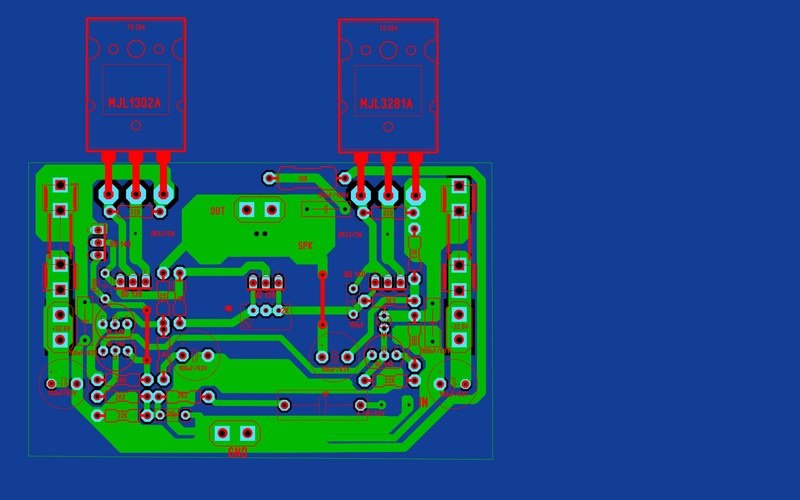
my pcb is very good, no common mistakes my friends....
But I also think that in a DIY forum, the most important thing should be DIY, only DIY.
if Mr. Elliot, that I appreciate a lot, publishes an amp schematic, with all the respect, I can make it by myself, and it is not a good thing that all require me to buy his boards or the result will be rubbish....in a DIY forum...
my pcb is very good, no common mistakes my friends....
yes, I get the point and I fully agree.
But I also think that in a DIY forum, the most important thing should be DIY, only DIY.
if Mr. Elliot, that I appreciate a lot, publishes an amp schematic, with all the respect, I can make it by myself, and it is not a good thing that all require me to buy his boards or the result will be rubbish....in a DIY forum...
my pcb is very good, no common mistakes my friends....
On the contrary !!! i could expect anyone to come up with a far better PCB than Rod made and anyone to come up with a better pcb than the ones i make for my personal use and taste ...
As said i have seen way too much garbage designed for P3A ...lets see yours i promise i will be tender ....😀😀😀😀😀
( i don't need details picture style will do )
Last edited:
Very well
Its a simple and fine lay out but as said fails to keep all the rules that apply to audio PCB
IMHO that is probably impossible one has to split his priorities ....
---current source for LTP is far away the closer the better
---100R/100nf is too close to the transistor not sure if this is OK
---Ground trace to zobel too long too thin
---Thickening ground goes to all around ground style rather than real star ground
---I don't like the way you supply outputs ...i don't like the trace running close to B of transistors for +rail and the zobel trace for the-rail
---looks neat but trust me this style of PCB can be done to look far better will require re arrangement for the looks while still keep the audio rules /...It can be done ( done it many times in teh past before understanding how critical was to get my caps closer to teh outputs )
---Understanding though how driver and vbe works ( means you ve done your reading) will take you there and excuse your other small mistakes ...
I like my bank close to the outputs ( no wiring at all ) 12.000uf each usually 2-3 cm close nice 2.2uf bypassing also very very close ...decoupling demands after that are very very low This is the way to go ...all the rest is half the way there ....
Well done
Last edited:
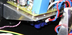
Here is a picture of my recently completed P3A. I made my own layout mostly to be able to use the components I already have, mainly the slightly grotesque 5µF 1100V input capacitors, it can now safely handle the offset voltage from broken valve preamps...
I use ground planes, two of them to be precise one around the outputs that handles local decoupling and output zobel network, the other is for all low signal ground, each ground plane have a separate cable to the central ground point.
The power supply uses two rectifiers and the two supply halves are brought together only at the central ground point. There is no audible hum at all with my normal speakers even if I put my ear next to the speaker maybe a faint hiss from the tweeter if the room is really quiet.
The first picture does not show the board with half of the capacitors and the central ground point very well, it hangs under the shelf that the amplifier boards are mounted on so the connections to the supply is very short maybe 4cm, here is an attempt to show it better.
Attachments

Very well
Its a simple and fine lay out but as said fails to keep all the rules that apply to audio PCB
IMHO that is probably impossible one has to split his priorities ....
---current source for LTP is far away the closer the better
---100R/100nf is too close to the transistor not sure if this is OK
---Ground trace to zobel too long too thin
---Thickening ground goes to all around ground style rather than real star ground
---I don't like the way you supply outputs ...i don't like the trace running close to B of transistors for +rail and the zobel trace for the-rail
---looks neat but trust me this style of PCB can be done to look far better will require re arrangement for the looks while still keep the audio rules /...It can be done ( done it many times in teh past before understanding how critical was to get my caps closer to teh outputs )
---Understanding though how driver and vbe works ( means you ve done your reading) will take you there and excuse your other small mistakes ...
I like my bank close to the outputs ( no wiring at all ) 12.000uf each usually 2-3 cm close nice 2.2uf bypassing also very very close ...decoupling demands after that are very very low This is the way to go ...all the rest is half the way there ....
Well done
many thanks for your comment.
Can I see yours now?😀
Have you listened to Rod's board and compare it with yours?
I've tried one channel with "battle" speakers and it sound really nice...but I think there is a hum issue, probably due to the input cable..I took it very short (about 8-10cm)...
Gotta try to short the input at first...
My Greek friend, do you think that using two diode bridges could help?
Gotta try to short the input at first...
My Greek friend, do you think that using two diode bridges could help?
- Home
- Amplifiers
- Solid State
- P3A Comparison table ( long .... )