Why not? bypass them with caps and you have essentially programmable resistors. The extra current for the AB portion comes from the large bypass cap, no? Even then I see tube data for cathode bias that says 90ma idle, 105 ma iMax, but in fixed it's 50ma, and iMax 150ma. In otherwords, shallow AB with a cathode resistor?
Bought in a power toroid 240VAC to 12VAC. I wired up the primary from a sig gen and monitored the output with a scope. Works very well and flat over the audio bandwidth right down to 10Hz.
So next step is to try it in a valve amp. So my next project is an EL84 push pull valve amp. Got the pcb just waiting for parts now.
So next step is to try it in a valve amp. So my next project is an EL84 push pull valve amp. Got the pcb just waiting for parts now.
I made a headphone amplifier with a 24V secondary transformer and a 6360 dual tetrode. Worked OK for a pair of Senn HD-650's.
No AB operation though, but if you don't mind being restricted to class A it's a good option.
I'm an apartment dweller and was happy with PP 2A3s in class A putting out a measly 6W continuous per channel. Apparently that's all I need. The Russian 6P43P tube (similar to EL86) has been touted as quite linear in triode, capable of 14W plate+screen dissipation, with rp well below 1000 ohms. Therefore, an OPT presenting 2k ohms p-p to 4 ohm load is in play for a PP class A triode amp; although for me, 3k:4 would be more attractive. I prefer the sound of more damping (I like 5k p-p for PP 2A3s, as opposed to the more commonly used 3.5k).
1) Can you share a schematic of your PP EL86 amp?
2) Assuming class A operation is OK -- In "Valve Amplifiers", Morgan Jones mentions that LM317 works fine as a constant current cathode load for output tubes once bypassed, since bypassing the CCS for AC makes the AC performance of the LM317 irrelevant. True? If so, why not simply set the current for each output tube using an LM317 bypassed with 100uF or so?
I wouldn't use an LM317 with EL86 - too close to it's voltage limit.
LM317-HV or TL783 work, the latter actually being obtainable easily.
LM317-HV or TL783 work, the latter actually being obtainable easily.
No worries, I have some TL783s handy.
Also, is there any reason why a resistor in series with an LM317 (and bypassed along with it) won't work to keep the IC within its 35V window of operation? I figure 100R would burn off 4.5V, which would make a difference for the LM317.
Or, put a single 47R 2W resistor below the LM317s, to lift the whole output stage roughly 4.7VDC above ground. Then put a LM317||100uF from the top of that 47R 2W resistor to each output triode's cathode. Since the 47R resistor would be common to both halves of the output tube pair, it might not need to be bypassed. Or bypass it if need be.
I was looking at availability of the Triad VPT230 xfmrs. They're readily available from Mouser. However, all I can find with this number are 2:1/1:2 isolation transformers (115/230V primary:115/230V secondary). I can't find any that are 230V:12V or 115:6V. How are the inductances of the VPT230 xfmrs relevant to the Triad toroids used as OPT?
Last edited:
Oops. Sorry for the dumb question. Answer = Read the thread!
For PP 6P43P, what VA for VPT12|| did you use? 25VA? 50VA? 100VA?
For PP 12AV5-triode. what VA did you choose?
--
Thanks.
I've used VPT series as OPTs with the following tubes: 6N13S PPP (VPT48--), 6P1P PPPP triode (VPT12||), KT120 triode (VPT18--), EL34 PP (VPT18--) regulated screens, 6P43P PP (VPT12||) triode, 6P3S PP (VPT12--) tetrode, and a 12AV5 PP triode, (VPT12||) all with excellent results. (-- = secondaries in series, || = parallel)
For PP 6P43P, what VA for VPT12|| did you use? 25VA? 50VA? 100VA?
For PP 12AV5-triode. what VA did you choose?
--
Thanks.
Last edited:
My go to is 100VA because Arrow has then for a good price, a set of 25VA will work fine with 6P43P.
I've used 50VA with the 12AV5, too. Again my go to is the 100VA.
My largest amps use a pair of 250VA per channel though.
How else can you build a stereo amp with good sound with only spending ~100$ on OPTs?
https://www.arrow.com/en/products/vpt12-8330/triad-magnetics
There's no reason a series resistor won't work with an LM317, but it'll fall out of regulation sooner that way.
Can you share some info about this 2-OPT scheme?
Is it for larger primary inductance? Does that create a problem with dc resistance?
Does it work with larger power PP amps? Like 50-100W?
Do you stack the toroids on top of each other to keep the footprint small? Does that create any electrical/magnetic issues? Do they get hot?
Does the pairing make a difference? I mean, using the windings from trafo A as the "outers" and trafo B as the "inners" vs the windings fom A as one "outer" and one "inner"?
You get more inductance. The DCR of even a pair of 25VA coils is still lower than the DCR of a normal OPT.
Yes, it works with higher power. My monoblocs make 113W RMS @ 30 Hz using a pair of 250VA coils (Primary DCR is only 12R across both coils)
I stack them to save space. They are both used as one so it doesn't matter RE: coupling. I wouldn't stack the OPT on the power transformer though 😀
It doesn't matter as long as they are in order.
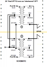
The way I connect them is as follows:
Y=yellow
K=black
BR=brown
BL=blue
P=purple
G=grey
O=orange
R=red
1=coil 1
2=coil 2
Y1 - Speaker positive
BL1 - Plate 1
P1, G2 - B+
BR2 - Plate 2
BR1 - P2
G1 - BL2
K1 - Y2
K2 - Speaker negative
R1 - O1
R2 - O2
This will connect everything in the right order electrically and magnetically.
I can't believe I have that memorized now!
EDIT: They get as warm as the chassis they are bolted to. They generally don't heat much from operation since the DCR is so low.
Yes, it works with higher power. My monoblocs make 113W RMS @ 30 Hz using a pair of 250VA coils (Primary DCR is only 12R across both coils)
I stack them to save space. They are both used as one so it doesn't matter RE: coupling. I wouldn't stack the OPT on the power transformer though 😀
It doesn't matter as long as they are in order.
The way I connect them is as follows:
Y=yellow
K=black
BR=brown
BL=blue
P=purple
G=grey
O=orange
R=red
1=coil 1
2=coil 2
Y1 - Speaker positive
BL1 - Plate 1
P1, G2 - B+
BR2 - Plate 2
BR1 - P2
G1 - BL2
K1 - Y2
K2 - Speaker negative
R1 - O1
R2 - O2
This will connect everything in the right order electrically and magnetically.
I can't believe I have that memorized now!
EDIT: They get as warm as the chassis they are bolted to. They generally don't heat much from operation since the DCR is so low.
Last edited:
Great info. Thanks. Did you try more than one brand of toroids? Any brand better than others? If so, in what way?
Tell me if I'm doing this right.
A 230V pri to 12V sec has a stepdown ratio of 19.167:1.
The stepdown ratio is the same as the turns ratio, so about 19:1.
A 19:1 turns ratio translated to impedance stepdown = 1.5k:4 (or 3k:8)
Since I have 4 ohm speakers, I think I'd rather see 3k:4
That's about 27.5:1 turns ratio, so...
Do I want to try something like a 230V:6V toroid? (I.e., wire the primaries in series and the secondaries in parallel.) That would yield a turns ratio of 38.33:1, or approx. 5.8k:4 ohms.
But now we're up there in impedance. I'm probably overthinking this, but I use 4 ohm speakers and a 1.5k ohm primary impedance is probably not going to work so great.
230V:9V = 25.56:1 = 2.6k:4 ohms, which should be just enough load on the 6P43P-triodes.
VPT18-2780 (50VA) or VPT18-5560 (100VA) would work for that, right?
--
--
Last edited:
The turns ratio is not quite the voltage ratio since the latter is quoted under load so a 230:6 in reality is closer to 230:7 as far as turns go.
Edit, actually for each winding, obviously.
Edit, actually for each winding, obviously.
Last edited:
I factor for 6R but my speakers will dip to 3R. The tubes can put out the current so I just use 2k2:6R.
Using VPT18 as you wrote would work fine. Your math is good. (((230/9)^2)*4)=2612.
I would always recommend using two interleaved for good bass response 🙂 For 6P43P the 25VA VPT18-1390 is big enough, too. OTOH for less than 100$US, you can get 4 of the 50's https://www.arrow.com/en/products/vpt18-2780/triad-magnetics
Last edited:
You get more inductance. The DCR of even a pair of 25VA coils is still lower than the DCR of a normal OPT.
Yes, it works with higher power. My monoblocs make 113W RMS @ 30 Hz using a pair of 250VA coils (Primary DCR is only 12R across both coils)
I stack them to save space. They are both used as one so it doesn't matter RE: coupling. I wouldn't stack the OPT on the power transformer though 😀
It doesn't matter as long as they are in order.
The way I connect them is as follows:
Y=yellow
K=black
BR=brown
BL=blue
P=purple
G=grey
O=orange
R=red
1=coil 1
2=coil 2
Y1 - Speaker positive
BL1 - Plate 1
P1, G2 - B+
BR2 - Plate 2
BR1 - P2
G1 - BL2
K1 - Y2
K2 - Speaker negative
R1 - O1
R2 - O2
This will connect everything in the right order electrically and magnetically.
I can't believe I have that memorized now!
I copied the schematic from the VPT12-8330 data sheet and drew in the connections you described above, then attached that drawing to this message. Does it look correct?
--
Attachments
- Home
- Amplifiers
- Tubes / Valves
- Output transformers a cheap alternative?