We are discussing about primary inductance of cheap toroidal PTs, and this point is crucial about the usefulness or not as OPTs.
Some folks have contributed with real measurements, so we need to know if those measurements have any sense or not.
Can we continue?
Some folks have contributed with real measurements, so we need to know if those measurements have any sense or not.
Can we continue?
Last edited:
This is why I use Triad xfmrs...
From Triad Magnetics:
Inductance depends on the drive level and the permeability of the core (which can vary significantly). Having said that, I have reviewed some history data from various lots and here are the results.
1. VPT230-110 = 213 to 439H @ 230V, 50Hz (primaries in series). 304H average from 15 samples.
2. VPT230-220 = 192 to 444H @ 230V, 50Hz (primaries in series). 283H average from 15 samples.
3. VPT230-430 = 93 to 214 @ 230V, 50Hz (primaries in series). 128H average from 15 samples.
It seems to me that those measurements looks good on paper, in real world practice you must measure at low voltage, Williamson did that at 5V RMS/50Hz
http://www.sowter.co.uk/pdf/Williamson%20Amplifier.pdf
Anyway, having so huge inductances, my guess is that at lower voltage you would obtain inductance on the order of tens H, which is in the ballpark of most SE OPTs.
So using cheap toroidal power transformers as output transformers seems plausible, but not to uncork champagne. 🙄
Inductance does not depend on VP-P. Indeed… you'll get the same inductance reading from a transformer's coils whether you excite it with a 10 millivolt or a 10 volt signal.
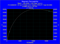
No, this is wrong, in PP transformers magnetic permeability and hence primary inductance depends on magnetic field applied, which in turn depends on applied voltage.
In the attachment you can see a graph made with measured values of EDCOR M6 lamination.
Primary inductance should have the same shape.
NO MATH, just measurements and a graph... 😉
Attachments
Last edited:
There is also an article with measurements on Steve Bench's site; if you go to Power amps, the link is a couple of paragraphs down. This is where I first saw this idea about 10 years ago.
There is also an article with measurements on Steve Bench's site; if you go to Power amps, the link is a couple of paragraphs down. This is where I first saw this idea about 10 years ago.
Thanks piano3; I remember but over the years it faded away.
The Inductance Bridge (construction project) - Part 1
Let's agree on the fact that induction is a function of core material, core geometry, frequency and applied AC, number of turns, and go on with what this thread is about.
IMO toroidal power supply transformers have a limited application for output transformers:
- no primary DC current allowed, so not suited for SE unless parafeed. In PP amps good DC current balance is needed.
- limited induction with low AC applied for high power toroids, limiting tube choice to low Rp types.
- low power toroids with enough induction limit output power, and high DC resistances can compromise the amp's performance.
- in general, though primary to secondary coupling can be very good in toroids (check Plitron output transformers for example), it is not very good in power supply toroids (single primary and secondary sections). High leakage inductances impair HF bandwidth.
Power supply toroids can not replace dedicated output transformers without compromise in quality.
Cheap? Yes...
Alternative? Depends on your expectations....
Last edited by a moderator:
I first tried it as a cheap experiment and my expectations were indeed very low. I used 6s19p outputs and 6e6p voltage amplifiers-no phase splitter as all my other stuff has differential outputs. High impedance cascode current sinks returned to a negative supply were used and the cathodes of the output stage were coupled with a single 15 uF film cap. Only small power supply decoupling caps were used at the anodes to discourage oscillation. I didn't need much power because of my Tannoy speakers so 6V secondaries were wired in parallel.
One of the results of this cheap experiment was that my expensive SE 300B amp from a world renowned British (formerly Japanese) manufacturer was simply given to my brother because I knew I would never listen to it again.
I recommend that anyone with sensitive speakers who has some series pass tubes or other suitable low impedance tubes should just get out their soldering irons and try it.
^ sounds like a good little build.
I just "auditioned" my all toroidal EL86 build last night, and it is ridiculous how good it sounds, and it makes some serious, tight bass. I really wish I had more measuring equipment than just a multimeter these days, as I'm very curious to see how it looks.
I just "auditioned" my all toroidal EL86 build last night, and it is ridiculous how good it sounds, and it makes some serious, tight bass. I really wish I had more measuring equipment than just a multimeter these days, as I'm very curious to see how it looks.
Let's agree on the fact that induction is a function of core material, core geometry, frequency and applied AC, number of turns...
Speak about transformer parameters without equations is like to speak about an amplifier without its schematic, and this is a technical forum, nevertheless I will not write more equations, people interested on them can see here
http://www.diyaudio.com/forums/tubes-valves/318391-help-troubleshooting-se-opt-2.html#post5427648
I must agree with you, what you say is consistent.
IMO toroidal power supply transformers have a limited application for output transformers:
- no primary DC current allowed, so not suited for SE unless parafeed. In PP amps good DC current balance is needed.
- limited induction with low AC applied for high power toroids, limiting tube choice to low Rp types.
- low power toroids with enough induction limit output power, and high DC resistances can compromise the amp's performance.
- in general, though primary to secondary coupling can be very good in toroids (check Plitron output transformers for example), it is not very good in power supply toroids (single primary and secondary sections). High leakage inductances impair HF bandwidth.
I would add high stray capacitance due to great external surface of toroids, which lead us to use the smaller ones.
Power supply toroids can not replace dedicated output transformers without compromise in quality.
Cheap? Yes...
Alternative? Depends on your expectations....
Again I agree with you, and my personal experience is that winding my own OPTs is cheaper, better and in some cases easier.
Valve amplifiers overall quality depend mostly on its OPTs, using toroidal PTs is an interesting experiment, but my conclusion is thumbs down.
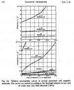
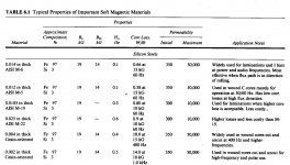
The Edcor M-6 permeability graph is interesting. One worrisome aspect is the apparent continuing drop in permeability below 5000 Mu at the low end. (notice small gap in curve on left) Although Bozorth's 3% Silicon steel graph shows just a factor of 10 drop in Mu going down to zero flux.
The LEM (Linearity Enhancement Module) graph seems to indicate a LOT more drop off!! If that's really the case, I could see some point in using the HF bias scheme (used in the LEM module)
Custom Analogue Audio: Joe Rasmussen Pages
--------------------------------
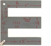
Also, long E laminations could be used to put two conventional (industrial xfmr pre-wound) bobbins onto one core, doubling the primary turns available. Secondaries could be paralleled. Making for a low cost OT alternative. (Lamination pic is of Thomas & Skinner lamination # EI-1 3/8 LSW )
The LEM (Linearity Enhancement Module) graph seems to indicate a LOT more drop off!! If that's really the case, I could see some point in using the HF bias scheme (used in the LEM module)
Custom Analogue Audio: Joe Rasmussen Pages
--------------------------------
Also, long E laminations could be used to put two conventional (industrial xfmr pre-wound) bobbins onto one core, doubling the primary turns available. Secondaries could be paralleled. Making for a low cost OT alternative. (Lamination pic is of Thomas & Skinner lamination # EI-1 3/8 LSW )
Attachments

Last edited:
Did you actually physically try it? Or are you basing that opinion on something unrelated to physically trying it?Valve amplifiers overall quality depend mostly on its OPTs, using toroidal PTs is an interesting experiment, but my conclusion is thumbs down.
My opinion is shared by others here, the results are excellent. The oscilloscope traces are cleaner than the Hammond 1650N I was using as a baseline. I posted traces earlier in this thread. including a clean sinewave at 125kHz.
The Bozorth 3% Silicon steel Mu graph starts at 4000 Mu and drops to 400 Mu at zero flux. (so filling in the small gap in the M-6 graph from Edcor, left corner) So that would be a total 100 X drop in Mu down to zero flux !! Apparently that (horrific) LEM Mu graph is for real.
Initial Mu Table: 50,000 Mu down to 350 initial Mu here (below):
So if these toroids are measuring 200 H at max voltage, that would be less than 2 H at tiny audio levels.
No more low level Bass detail.
That LEM module is looking kinda useful now. Just need enough HF to reach 100 gauss.
Initial Mu Table: 50,000 Mu down to 350 initial Mu here (below):
So if these toroids are measuring 200 H at max voltage, that would be less than 2 H at tiny audio levels.
No more low level Bass detail.
That LEM module is looking kinda useful now. Just need enough HF to reach 100 gauss.
Attachments
Last edited:
Low Mu OT material, at low signal, just means more magnetizing current of course. So the output Z of the tubes needs to be able to produce 100 Gauss in the OT without significant Voltage distortion (low Zout). That's about 1% of max signal current (1/100 of 10,000 Gauss max) demanded to fix the core material deficiency. N Fdbk would do the job too.
The LEM thing can be done using a double Op Amp., so is probably of similar effort to using some local N Fdbks on the output tubes.
The LEM thing can be done using a double Op Amp., so is probably of similar effort to using some local N Fdbks on the output tubes.
Attachments
Last edited:
95%(at least) of my listening is LP's and 78's. When I was experimenting with capacitor values for coupling the cathodes of the (enforced current balanced) differential power stage, it quickly became apparent that a value of 20 uF or more caused low frequency artefacts in the record material which one had never noticed before to become prominent. I imagine this would also happen with a parafeed topology.
Local NFB is great with your favoured Sweep tubes, smoking-amp, but wouldn't seem to be so helpful with a regulator triode with a mu of 2, or would it?
Local NFB is great with your favoured Sweep tubes, smoking-amp, but wouldn't seem to be so helpful with a regulator triode with a mu of 2, or would it?
Those regulator (Mu like 2 to 4 range) already have low output Z. The low Mu wouldn't provide any appreciable local loop gain for more N Fdbk. But a high gain driver tube in the loop could work.

I think it has to do with the winding ratio being lower, and the low Zout of the power tubes but I'm no expert. All I know is this design makes 6W RMS sine, and more for music, using 25VA $37CAD coils... It's also powered from 12V using DC boost converters. At 1W output the frequency response is +-1db 6Hz-125Khz sine.
Last edited:
i have what seems to be 2 x 440 volt toroids that i will try one day, i will have to wind secondaries too so i can use them...Did you actually physically try it? Or are you basing that opinion on something unrelated to physically trying it?
My opinion is shared by others here, the results are excellent. The oscilloscope traces are cleaner than the Hammond 1650N I was using as a baseline. I posted traces earlier in this thread. including a clean sinewave at 125kHz.
a lot of fine work on toriods here by m. vanrdervin.....meno vanrdervin toroid output transformers - Google Search
Modern High-end Valve Amplifiers: Based on Toroidal Output Transformers: I.R.Menno Van Der Veen: 9780905705637: Amazon.com: Books
- Home
- Amplifiers
- Tubes / Valves
- Output transformers a cheap alternative?