You know, I'm sure some of you out there are fellow smokers. I think it's time we have a "biggrin" smiley of our own.
Here ya go.
Smoke 'em of you've got 'em. 🙂
se
Here ya go.
An externally hosted image should be here but it was not working when we last tested it.
Smoke 'em of you've got 'em. 🙂
se
Re: Whom to believe?
Actually, these two things don't exclude each other. My amp, which is based largely on the Elektor Ulti-amp topology (common emitter output stage!) but uses different transistors and different values (currents, compensation points), has about 3.5 MHz loop bandwidth and (without the input filter) some very high slew rate. With the 150 kHz input filter in place (and an air coil of five turns in series with the output), it can drive a square wave into about any load, whether resistive, capacitive or inductive, or a combination thereof. Getting the compensation right was a pain, but it's been running for five years with various speakers. It only blows the fuses when I short the output while experimenting with speakers...
Fred Dieckmann said:... but stability into widely varying load impedances is much more important than high slew rate or bandwidth far exceeding the audio range. Most of the good amps I have heard have closed loop bandwidths in the 100 kHz to 200 kHz region and conservative phase margins.
Actually, these two things don't exclude each other. My amp, which is based largely on the Elektor Ulti-amp topology (common emitter output stage!) but uses different transistors and different values (currents, compensation points), has about 3.5 MHz loop bandwidth and (without the input filter) some very high slew rate. With the 150 kHz input filter in place (and an air coil of five turns in series with the output), it can drive a square wave into about any load, whether resistive, capacitive or inductive, or a combination thereof. Getting the compensation right was a pain, but it's been running for five years with various speakers. It only blows the fuses when I short the output while experimenting with speakers...
Re: Whom to believe?
.....people......why does Fred always look for ways to misrepesent me????
fred.........i did not say stability is unimportant....(indeed i would suggest its mandatory)....neither did i say very high slew rate's are in any way necessary...indeed earlier in the thread i suggested a 400V/uS slew is wholly unnecessary...
Fred Dieckmann said:I think I will take the word of some who actually designs and sells a highly regarded amplifier over someone likes to quote technical articles without the experience of actually building and measuring amplifiers. It may come as a shock..... but stability into widely varying load impedances is much more important than high slew rate or bandwidth far exceeding the audio range. Most of the good amps I have heard have closed loop bandwidths in the 100 kHz to 200 kHz region and conservative phase margins. I guess it is a lot easier to read about something than to actually go do it though. Arrogance and ignorance are two traits that don't go together very well in my experience.
.....people......why does Fred always look for ways to misrepesent me????
fred.........i did not say stability is unimportant....(indeed i would suggest its mandatory)....neither did i say very high slew rate's are in any way necessary...indeed earlier in the thread i suggested a 400V/uS slew is wholly unnecessary...
Re: Re: Re: Re: Re: Re: a big enough liabilities
🙂
dave
Steve Eddy said:Whatever gets your foot tapping is the only "right" approach.
🙂
dave
Re: Re: Re: ....Interesting....
Not to ZIP gifs (or jpgs) is the answer.
dave
mikek said:...to zip or not to zip...that is the question...😀
Not to ZIP gifs (or jpgs) is the answer.
dave
Re: Re: Re: Re: ....Interesting....
.....fair enough dave....🙂
planet10 said:
Not to ZIP gifs (or jpgs) is the answer.
dave
.....fair enough dave....🙂
Re: Re: Whom to believe?
I meant to write emitter follower, i.e. common cathode - sorry!
Mikek, are you trying to provoke Fred into loosing his temper? I consider some of your posts here on the border of being rude. Fred may have strong opinions, but he certainly is not clueless or deluded!
capslock said:
Elektor Ulti-amp topology (common emitter output stage!)
I meant to write emitter follower, i.e. common cathode - sorry!
Mikek, are you trying to provoke Fred into loosing his temper? I consider some of your posts here on the border of being rude. Fred may have strong opinions, but he certainly is not clueless or deluded!
Steve,
I'm working on it........
But getting some efficiency is a big challenge. My original design pulled 150W of heat from the wall socket and delivered just 28W of audio. This new design pulls 94W and hopefully will deliver 42W, but to achieve this requires some clever tricks, including sliding bias. This is a challenge, since stability becomes a major factor, but the great advantage of non-switching output devices is very clear. Global negative feedback is not used, though there is a very large local feedback stage. I'll keep you posted........
Cheers,
Hugh
Re: Re: ....Interesting....

www.aladdinsys.com
PS: Not very clever to compress compressed picuters DS.
Many PC owners think it's time consuming to zip and unzip files. Since a decade I have used StuffIt Expander and DropStuff (and DropZip) to compress files. This is Mac software but luckely all PC owner can enjoy this cool software. When I got my P4 I immediately got DropStuff and StuffIt Expander for Windows. Just drag the files/folder to the icon at your desktop - swisch - the file is compressed. Can it be easier?Steve Eddy said:Why are you ZIPping up GIFs? I spent far more time firing up WinZip and unZIPping it than that 1% compression saved me in downloading it.
www.aladdinsys.com
PS: Not very clever to compress compressed picuters DS.
Re: Re: Re: ....Interesting....
It's not really that time consuming for PC users. I just click on the attachment link, tell Windows to open the file from the current location, WinZip displays the file in the Zip which I just double click on and the appropriate application (i.e. Photoshop if it's a grahic or Acrobat if it's a pdf) fires up and displays it.
Even though this doesn't take much time at all, my point was that even this little bit of time is more than the next-to-no additional compression that ZIPping the file saves in downloading it.
In other words, ZIPping compressed files just adds a needless intermediate step.
se
peranders said:Many PC owners think it's time consuming to zip and unzip files. Since a decade I have used StuffIt Expander and DropStuff (and DropZip) to compress files. This is Mac software but luckely all PC owner can enjoy this cool software. When I got my P4 I immediately got DropStuff and StuffIt Expander for Windows. Just drag the files/folder to the icon at your desktop - swisch - the file is compressed. Can it be easier?
It's not really that time consuming for PC users. I just click on the attachment link, tell Windows to open the file from the current location, WinZip displays the file in the Zip which I just double click on and the appropriate application (i.e. Photoshop if it's a grahic or Acrobat if it's a pdf) fires up and displays it.
Even though this doesn't take much time at all, my point was that even this little bit of time is more than the next-to-no additional compression that ZIPping the file saves in downloading it.
In other words, ZIPping compressed files just adds a needless intermediate step.
se
AKSA said:I'm working on it........
But getting some efficiency is a big challenge. My original design pulled 150W of heat from the wall socket and delivered just 28W of audio. This new design pulls 94W and hopefully will deliver 42W, but to achieve this requires some clever tricks, including sliding bias. This is a challenge, since stability becomes a major factor, but the great advantage of non-switching output devices is very clear. Global negative feedback is not used, though there is a very large local feedback stage. I'll keep you posted........
Thanks.
Yup. There's no free lunch here. The approach I'm taking is to move the efficiency to the loudspeaker end and reducing the required output power from the amplifier. Every 3dB increase in speaker efficiency means half as much power from the amplifier for a given output.
Also I'm using the active devices just for current gain, not voltage gain, which will be achieved passively.
In the simplest version, we're talking about 4 watts using 7 parts. I'm thinking of dubbing it The 47 just to tweak the Gaincard folks. 🙂
se
Re: a big enough liabilities
from post#32
so......mrfeedback, if fred's 'experiance' is vastly superior to my 'ignorance', how come the man is unaware of the fact that secondary breakdown and MOSFET's is oxymoronic..?
to obtain an elementary electronic engineering qualification where i come from, you need to be acquainted with the such elementary stuff....🙄....
...to think that he's called me arrogant and ignorant.......without provocation.....HA!
...you appear not to accept that the contents of my 'profile'......ergo, my CV are none of your business.......untill i decide otherwise? 🙄
from post#32
Fred Dieckmann said:
The output stage is not likely to go into thermal runaway at about 60 mA bias for each fet, but short circuits on the output with no source resistors are very likely to destroy output devices.
so......mrfeedback, if fred's 'experiance' is vastly superior to my 'ignorance', how come the man is unaware of the fact that secondary breakdown and MOSFET's is oxymoronic..?
to obtain an elementary electronic engineering qualification where i come from, you need to be acquainted with the such elementary stuff....🙄....
...to think that he's called me arrogant and ignorant.......without provocation.....HA!
mrfeedback said:
I have politely asked you TWICE as to the meaning of the gibberish on your profile page and TWICE recieved from you impertinantly rude replies.
...you appear not to accept that the contents of my 'profile'......ergo, my CV are none of your business.......untill i decide otherwise? 🙄
mikek said:
..the failure mechanism in that case has nothing to do with 'thermal runaway' i fear....🙄
The prosecution rests😎
Well you should be well aquaintted with the fact that mosfets (excluding lateral mosfets) generally exhibit a +ve temp coefficient upto quite a high Id. So they are technically venerable to thermal runaway in many applications .... particularly in constant power applications.
AudioFreak said:
Well you should be well aquaintted with the fact that mosfets generally exhibit a +ve temp coefficient upto quite a high Id. So they are technically venerable to thermal runaway in many applications .... particularly in constant power applications.
not thermal runaway i am afraid....🙂....
..this is a bipolar problem resulting from secondary breakdown....ergo..current hogging from which MOSFET's are effectively immune......
MOSFET's like bipolar devices, are of course vulnerable to destruction due to overdissipation...(who isnt?)...has nothing to do with thermal runaway though...
Go have a read of a few of the datasheets available with regard SMPS design and mosfets. I believe there is one on IR's website .... it is totally to do with thermal runaway. ie. the device gets hot and conducts more which makes it hotter and so on until it goes bang. Internally, it may work in a different fashion to BJT's but failure is still the result of thermal runaway.
AudioFreak said:Go have a read of a few of the datasheets available with regard SMPS design and mosfets. I believe there is one on IR's website .... it is totally to do with thermal runaway. ie. the device gets hot and conducts more which makes it hotter and so on until it goes bang. Internally, it may work in a different fashion to BJT's but failure is still the result of thermal runaway.
ok dan... i will...🙂
advice
Arrogance does not bother me a bit ....... if you have the knowledge to back it. The failure mode I was referring to was excessive peak current into a short. An IRF240 has an on resistance of 0.18 ohms. with a 40 volt supply you have a peak current of about 220 amps. With a 1 ohm source resistor the current is about 34 amps. The same advice holds for bipolars. MOSFETs have a Safe Operating area just as bipolars do. They can also go into thermal runaway just as bipolars can. Reliability concerns are pretty much the same ones as bipolars with the addition of clamping excess gate to source voltage with a zener.
You seem to have a major twist in your shorts about something. I suggest a couple Valium or getting laid; if that's an option for you. Ignore those who tell you to be civil to me. I find your rants hysterical and I can always use good laugh. Besides, I thrive on conflict, ask around.
Re: advice
...which constitutes 'thermal runaway in your book..?
😀😀😀😀😀😀😀😀😀😀😀😀
Fred Dieckmann said:The failure mode I was referring to was excessive peak current into a short.
...which constitutes 'thermal runaway in your book..?
😀😀😀😀😀😀😀😀😀😀😀😀
Re: Re: Slew rate etc
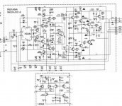
...an example of such an approach from mcp's site:
http://www.ampslab.com/bi300schema.htm
mikek said:The hypothetical op-amp., G1, (see attached), with a slew rate of 40V/uS, is connected to an output stage, G2, with a gain of 10, and the whole is enclosed in global feedback loop, giving an overall closed loop gain of 40.
It is straightfowardly demonstrated that the output slews at approx. 400V/us. This obviously assumes that the output stage possess a slew rate well in excess of this figure, otherwise the overall slew rate is then determined by the output stage.
This is almost invariably the case, and should therefore not be a concern.
mikek said:
Hi Jan 😀 ,
O.K...Most designs of this type run the output stage in common emitter mode....this is essentially a bad idea, because the global feedback loop ceases to track the output when the amp. is driven into clip, ergo the output tends to latch up to one or other supply rail.
Moreover, output stage bias stability in some of these schemes is rather suspect......
A much better scheme, which preserves the advantages of an output stage with gain, without the latch-up problem, is one in which a push-pull complementary Wilson mirror, biased into class A, (a la Alexander amp.), is used to generate the output stage gain. The output stage proper can then be a traditional unity gain follower.
I do not however recommend the current feedback technique used in the Alexander amp.
...Oh...and the complementary Wilson mirror can be biased into class A with a negative feedback bias generator...with the Vbe multiplier used to bias just the output stage...😎
Another advantage with using an output stage with gain greater than unity, is that the main input gain stage runs on lower supply rails......and can thus be a discrete op. amp., with high quality, high ft transistors.
These tend to be available mainly in low-voltage specs....Non-dominant poles can be therefore be relegated well beyond the unity gain bandwidth of the amp., making the whole easier to stabilise.....
...an example of such an approach from mcp's site:
http://www.ampslab.com/bi300schema.htm
Attachments

- Status
- Not open for further replies.
- Home
- Amplifiers
- Solid State
- Output stages with gain Enhance Slew rate