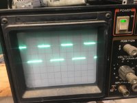
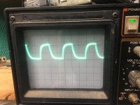
Is the drive signal on the gate pads going all of the way to ground (scope must be on DC coupling and the trace aligned to the reference line)?
Yes it was blowing the fets in all 4 banks as soon as I applied remote a fet would blow I cut the bad fet out and try powering it up again and it would blow another fet .
It did this in all 4 banks .
Wondering if I have a intermittent short or a bad solder connection on the driver board .
It did this in all 4 banks .
Wondering if I have a intermittent short or a bad solder connection on the driver board .
It's possible that a ground connection is intermittent. That's why it's so important to use ChipQuik.
Re-check all 4 banks and while watching the drive at the FETs (with the cap), move the driver board to see if the drive signals ever change.
Re-check all 4 banks and while watching the drive at the FETs (with the cap), move the driver board to see if the drive signals ever change.
I can’t get the drivers be signals to change while wiggling the driver board and pushing on various points of the board .
I never removed the power supply driver board the problem was with the output section .
I will replace the fets and see what I come up with
I never removed the power supply driver board the problem was with the output section .
I will replace the fets and see what I come up with
Here is what I get on the 494
Pin 1:4.99
Pin 2:0.05
Pin 3:0.00
Pin 4:1.47
Pin 5:3.73
Pin 6:0.00
Pin 7:13.47
Pin 8:4.96
Pin 9:5.30
Pin 10.5:30
Pin 11:13.47
Pin 12:13.47
Pin 13:4.99
Pin 14:4.99
Pin 15:4.99
Pin 16:0.00
13.47v on pin 7 error?
I’m double checking the 494 voltages and I know the pin order is correct . Here is what I get .
Pin 1:4.99
Pin 2:0.05
Pin 3:0.00
Pin 4:1.47
Pin 5:3.73
Pin 6:0.00
Pin 7:13.33
Pin 8:4.91
Pin 9:5.35
Pin 10:5.25
Pin 11:13.33
Pin 12:13.33
Pin 13:4.99
Pin 14:4.99
Pin 15:4.99
Pin 16:0.00
There are no fets in the amp right now .
Isn’t pin 7 suppose to be 0 volts why do I get 13 volts on it ? I’ve triple checked the pin order
Here's the problem. If you have 5v on pin 14, there is virtually no way that you can have 13v on pin 7.
If you had 5v on pin 1, and 0v on pin 2, pin 3 would be at something near 5v.
Pins 8 and 11 are directly connected and they would have the same voltage.
If you had 5v on pin 1, and 0v on pin 2, pin 3 would be at something near 5v.
Pins 8 and 11 are directly connected and they would have the same voltage.
Ok I guess I need to go back to school and learn how to look at the ic
I was measuring voltages from the back side of the power supply board and you are correct I had the pin order wrong .
I skipped over pin 1 and thought pin 2 was pin 1 so pin 8 was also skipped over .
I believe the ic is working correctly once the new fets come in I will replace them and power it up with a current limiter to see if I have any further issues
Got the new fets today .
I installed them and so far so good .
How long should I let the amp idle to make sure the fets are gonna survive ?
No outputs are installed yet
I installed them and so far so good .
How long should I let the amp idle to make sure the fets are gonna survive ?
No outputs are installed yet
First of all, clamp everything down to the heatsink.
Then I'd push/pull/twist everything, before and after heating/cooling various components. This is extreme but having the PS FETs blow one by one is odd. The only time I remember anything similar was on the larger Rockford amps like the old 800a2. That was due to driver issues.
Then I'd push/pull/twist everything, before and after heating/cooling various components. This is extreme but having the PS FETs blow one by one is odd. The only time I remember anything similar was on the larger Rockford amps like the old 800a2. That was due to driver issues.
This amp sucks .
I checked the drive signals on the outputs all appear good .
I put try outputs back in the amp and clamped everything down.
The amp will power up and idle for about 20 secs then it just starts blowing outputs .
I don’t get it all of the transistors on the driver boards are brand new .
I checked the drive signals on the outputs all appear good .
I put try outputs back in the amp and clamped everything down.
The amp will power up and idle for about 20 secs then it just starts blowing outputs .
I don’t get it all of the transistors on the driver boards are brand new .
- Home
- General Interest
- Car Audio
- Orion XTR PRO 2400