I removed the jumper from the 074 cause when it was in place and I had all of the outputs in the amp it blew them instantly .
So I bought another batch of outputs and removed the jumper now it will blow outputs after 30 secs .
So I bought another batch of outputs and removed the jumper now it will blow outputs after 30 secs .
Ok so at this point what should I do since the power supply is surviving .
Do I remove the outputs again and test as I did previously or leave the outputs in the amp and jump pins 13 to 14 on the TL074 and look at the drive signals ?
Do I remove the outputs again and test as I did previously or leave the outputs in the amp and jump pins 13 to 14 on the TL074 and look at the drive signals ?
I don't know what's happening. Without r-r oscillation, the FETs shouldn't be heating up.
What's the gate to source DC voltage on the output FETs. They should all be very near 0v with no oscillation.
What's the gate to source DC voltage on the output FETs. They should all be very near 0v with no oscillation.
On 1 side of the amp I get very close to 0 volts from gate to source on both the 640/9640.
The other side of the board I get very close to 0 volts from gate to source on all of the 9640’s the teasing is like 0.3 volts
On the 640’s on 1 side of the amp from gate to source I get 8 volts
Q942,941,442,441 is where I get the 8 volts from gate to source
The other side of the board I get very close to 0 volts from gate to source on all of the 9640’s the teasing is like 0.3 volts
On the 640’s on 1 side of the amp from gate to source I get 8 volts
Q942,941,442,441 is where I get the 8 volts from gate to source
Re-check the drive circuit for the FETs with 8v.
Use the circuit in the following SM for a reference:
http://www.bcae1.com/temp/bp1200p1_sm.pdf
Use the circuit in the following SM for a reference:
http://www.bcae1.com/temp/bp1200p1_sm.pdf
So both audio boards should be the same correct ?
1 board controls 2 banks of outputs and the other board controls the other 2 banks ?
If this is how it is set up then I will have to measure voltages and possible pull the boards and see what’s wrong with 1 of the boards
1 board controls 2 banks of outputs and the other board controls the other 2 banks ?
If this is how it is set up then I will have to measure voltages and possible pull the boards and see what’s wrong with 1 of the boards
Do you have a schematic or pics of the audio driverboards ?
I don’t get why I have 8 volts from
Gate to source only on a couple of outputs .
I have checked everything and it tests good wondering if I put something in the wrong location .
I don’t get why I have 8 volts from
Gate to source only on a couple of outputs .
I have checked everything and it tests good wondering if I put something in the wrong location .
I don't have a diagram for this amp but it's basically the same as the BP1200 amp that I posted the service manual for earlier in the thread.
The problem with the 8 volts between gate and source is most likely on the audio driverboards ? And not the other board with the LM361 ?
I install 1 driver board at a time and both of them cause the same issue .
The only thing that hasn’t been replaced on them is the diodes marked C3
Do you happen to know a part number for these ?
Since the schematic you posted the board locations do not match up to the driverboards in this amp
I install 1 driver board at a time and both of them cause the same issue .
The only thing that hasn’t been replaced on them is the diodes marked C3
Do you happen to know a part number for these ?
Since the schematic you posted the board locations do not match up to the driverboards in this amp
When doing repairs on car amps, you rarely get an exact diagram. The circuit is basically the same.
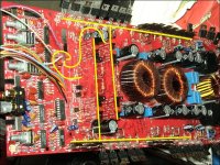
Use the markup feature of your PDF software to mark the part numbers in the orion.
Confirm that you have the emitters read low resistance to the gates. Confirm the rest of the connections.
Confirm that you have 12v across the collectors of all of the drivers.
Confirm that you have a strong signal on the bases of the drivers...
I don't know what C3 is in the amp.
Here are the voltages that are on the LM361 and the other IC marked F16
Do these voltages appear to be correct ?
LM361N
Pin 1:11.86
Pin 2:0.00
Pin 3:-7.65
Pin 4:-1.13
Pin 5:0.01
Pin 6:-11.77
Pin 7:0.00
Pin 8:2.79
Pin 9:2.80
Pin 10:-1.86
Pin 11:-1.71
Pin 12:0.00
Pin 13:2.80
Pin 14:2.83
F16
Pin 1:5.91
Pin 2:5.91
Pin 3:5.98
Pin 4:5.98
Pin 5:5.86
Pin 6:6.02
Pin 7:5.95
Pin 8:0.00
Pin 9:5.51
Pin 10:6.21
Pin 11:6.24
Pin 12:0.00
Pin 13:5.91
Pin 14:5.91
Pin 15:5.94
Pin 16:11.87
I ask this because everything else checks ok
Ok I checked both driverboards and everything checks fine and they line up with the schematic as far as parts placement .
I reinstalled the driverboards and the 8 volts only shows up when I push on the main board .
I have a broken connection somewhere
I reinstalled the driverboards and the 8 volts only shows up when I push on the main board .
I have a broken connection somewhere
I guess that wasn’t it either .
I don’t understand why I get 8 volts from gate to source on 1 bank of outputs .
If I only put one driver board in at a time I bet the problem on 1 bank of I remove that driverboard and replace it with the other driverboard the problem is still there .
I don’t understand why I get 8 volts from gate to source on 1 bank of outputs .
If I only put one driver board in at a time I bet the problem on 1 bank of I remove that driverboard and replace it with the other driverboard the problem is still there .
If you are testing without the outputs, you have to solder the jumper (pins 13-14) onto the op-amp on the audio PWM board to have the same drive to all outputs.
4v amplitude on a scope or 4v measured with a miltimeter?
Why did you think that you had an intermittent connection?
Why did you think that you had an intermittent connection?
I reinstalled both driverboards now I get 4 volts on all of the outputs from gate to source . Red probe on gate black probe on source .
I’m measuring them with a multimeter .
I thought I had a intermittent connection since when I pushed on the board the voltage would drop to 0 then climb back up to 8 volts .
I’m measuring them with a multimeter .
I thought I had a intermittent connection since when I pushed on the board the voltage would drop to 0 then climb back up to 8 volts .
- Home
- General Interest
- Car Audio
- Orion XTR PRO 2400