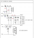
Ok - I made a stab at the layout of the xover based on the pictures posted. Note that I have labelled the changes in Red and marked the inductor numbers in blue and have also marked the colour of the wires used.
All the cap values are the same, but there are some resistor values that have changed as well as an additional resistor added to the tweeter network before the 184 inductor.
If anyone else can check my work, that would be great.
All the cap values are the same, but there are some resistor values that have changed as well as an additional resistor added to the tweeter network before the 184 inductor.
If anyone else can check my work, that would be great.
Attachments
I would but I cant open the first pic of the front of the board 🙁.Ok - I made a stab at the layout of the xover based on the pictures posted. Note that I have labelled the changes in Red and marked the inductor numbers in blue and have also marked the colour of the wires used.
All the cap values are the same, but there are some resistor values that have changed as well as an additional resistor added to the tweeter network before the 184 inductor.
If anyone else can check my work, that would be great.
Regards
Chris
Thanks,I have no problem opening it up, but I can post it again for you.
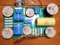
Initially this did not work either so I logged out and back in again and now both links work 🙂. Couple of questions.. At the bottom of the pic of the front of the board the wires are covering the board and a bit of a jumble what is connected to what?
Also what are the dimensions of the board?
Thanks
Regards
Chris
Thanks,
Initially this did not work either so I logged out and back in again and now both links work 🙂. Couple of questions.. At the bottom of the pic of the front of the board the wires are covering the board and a bit of a jumble what is connected to what?
Also what are the dimensions of the board?
Thanks
Regards
Chris
The bottom wires are the output, starting from image right: Woofer is red, black. The middle wires are tweeter, which are white and yellow, and the left
are for the midrange, which are green and orange. The output corresponds with the input. Input connections at the top of the picture are also, from the right of the image, woofer, tweeter, midrange.
The board is just about 8" x 12".
cafe latte- I measured the board for you and the exact measurement in our weird inch system is 8.25" x 13.25", or, to join the rest of the world, 210mm x 345mm.
Thanks really appreciated. I want to draw a component overlay diagram so I have a plan for etching the boards. The only issue I had so far is were all the wires are bunched up at the bottom all the connections are not that clear. I am busy for the next few days, but I will get back onto it when I have time and hopefully it will be some use.cafe latte- I measured the board for you and the exact measurement in our weird inch system is 8.25" x 13.25", or, to join the rest of the world, 210mm x 345mm.
I wonder of the two circuit diagrams we have which is the most recent?
Regards
CL
According to the seller, which of course could be fact or fiction, these xovers came from 2 year old SCM50s he had that had cabinet damage after a move. I saw that he had listed the woofers and mids on Audiogon etc. after the crossover sale. I've had them about 9 months.
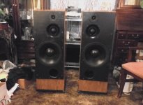
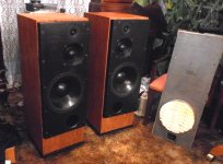
Moderators, feel free to slap me for posting this link of my finished speakers in action. I've been updating my progress for a while here on this thread. Don't know if it's appropriate or annoying, but here they are.
HERBIE MANN STANDING OVATION AT NEWPORT MUSHI MUSHI AND COMIN' HOME BABY - YouTube
HERBIE MANN STANDING OVATION AT NEWPORT MUSHI MUSHI AND COMIN' HOME BABY - YouTube
Hi,
Anyone can help me with the plans of construction of the speakers?
I have modeled mine with WinISD, but I need if anyone can help me with original dimensions x, y, z. (internal)
1 inch MDF?
And where to place the internal reinforcements?
I read somewhere that many reinforcements/insulation tend to lose bass?
I hope anyone can give me some light about this.
SCM100 or SCM50 drawing information, to build my clone without errors.
Thanks !!
I can't give you factory specs. I just braced the cabinets until I got down to 100l internally not including driver and crossover displacement. I used a 100 x 200mm PVC soil pipe from a garden store for the port. I would line the interior walls with egg-crate or similar foam. I think my bass is balanced with the other drivers and it seems like it sounds like it should be without the benefit of comparison with real SCM100 or software evaluation.
The SCM150 was made also in a 60 or 65 liter (not sure) sealed version for club/hall use. I wonder if the same cabinet ratio (can't remember exactly, but it's about 45% volume difference between the 150 and 65) could be used to build more compact, lighter, sealed cabinet SCM100s? Because the 100s are awfully big and heavy when it's time to move them.
The SCM150 was made also in a 60 or 65 liter (not sure) sealed version for club/hall use. I wonder if the same cabinet ratio (can't remember exactly, but it's about 45% volume difference between the 150 and 65) could be used to build more compact, lighter, sealed cabinet SCM100s? Because the 100s are awfully big and heavy when it's time to move them.
Last edited:
This thread is fantastic. I have just spent more money than I have ever spent before, on the drive units from the wilmslow audio k50 kit. I want to build the crossovers myself, and design the cabinets with an a-symetrical internal crossection to cut down on cabinet resonance. I have learned a lot just reading through this thread, and seeing the pictures posted by some of the users has got me really excited about the project! Sadly there is a 6 week wait on the drive units, but I will start work on the cabinet design and construction whilst waiting. If anyone has the dimensions for the cut outs for the baffle that would be of a huge help, and if anyone is interested I will post the cabinet designs once they are complete for people to look at.
I checked again with ATC and the 16 ohm mid is in BOTH the passive and the active. I am thinking to annoy the missus 😀 and buy the active amp units.
Regards
CL
Can the active amp units be purchased from ATC?
Yes as far as I am aware you can. I know for sure they sell active amps that can be connected to any of their speakers but as they sell the crossovers and drivers I am sure they sell the active units too. Just give them a ring.Can the active amp units be purchased from ATC?
Regards
Chris
Yes as far as I am aware you can. I know for sure they sell active amps that can be connected to any of their speakers but as they sell the crossovers and drivers I am sure they sell the active units too. Just give them a ring.
Regards
Chris
Will do, cheers. Did you end up making your own passive x-over?
thanks for the info on the filter ,i'm building a pair off scm100psl pro ,and got the original filters for the scm50psl ,the resistors are different on scm50 and scm100 all other components are the same
i realy apriciate this
regards frede
i realy apriciate this
regards frede
Hi, Frede4500,
where you got your crossover?
brand new from Wilmslow UK?
would you mind to post a closeup pictures for your crossover? thanks!
where you got your crossover?
brand new from Wilmslow UK?
would you mind to post a closeup pictures for your crossover? thanks!
The active version uses 16 ohm because it has the same amplifiers 200W for the bass (8 Ohm)and midrange (16 ohm) for cutting costs down I suppose as It really doesnt matter in active crossover. Making it 200+100+50=350 W per speaker.
The passive version uses 8 ohm midrange for an ease of build of the passive crossover as the rest of the drivers are also 8 ohm.
The passive version uses 8 ohm midrange for an ease of build of the passive crossover as the rest of the drivers are also 8 ohm.
No, sorry I did not mean that. The bass unit used in the Wilmslow kits and in the ATC version is 8 ohms, but the mids are 16 ohms. I was told that the 16 ohm mids have always been used rather than 8 ohms. Nobody has given me a good explanation why though as ATC do make an 8 ohm version, but the 16 ohm is there standard unit.
Regardles the wilmsolw k100s do sound very good, but must be lined with foam whatever anyone tells you.
Regards
CL
Last edited:
- Home
- Loudspeakers
- Multi-Way
- original crossover schematics for clone ATC SCM 100