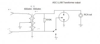
Well, the transformer sums up signals from both opamps, + and - signals. The immediate improvement in the sound is in the bass level and articulation - no more muddiness.
Removed C17 and C18 from digital inputs 1 and 2 (we absolutely don't need capacitance there)
removed C269 and C264, those are HF filtering caps - snip snip.
Why did you deem it necessary to remove these? Have you thought about what function they perform?
No offense, but it looks more like you've selected a few components randomly which won't stop it working for no reason.
Why did you deem it necessary to remove these? Have you thought about what function they perform?
No offense, but it looks more like you've selected a few components randomly which won't stop it working for no reason.
No offence taken...I know exactly what function those caps perform, they should not be there.
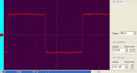
Those caps on digital inputs were probably put to filter out HF noise. Problem is that they also add to cable capacitance that would cause an "overshoot" of square digital signal.
Those caps on analog outputs were put to filter out HF noise as well, that is already done by signal processing components up the signal chain.
...my mistake, caps on digital inputs add to cable capacitance and cause signal not to "overshoot" but to become "saw-tooth".
Why did you deem it necessary to remove these? Have you thought about what function they perform?
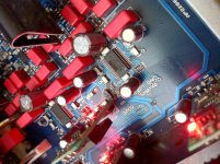
Take a look at the picture. They are screwing up the signal.
Attachments
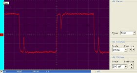
Take a look at the picture. They are screwing up the signal.
Interesting - is that the digital input? Do you have the before and afters? They shouldn't really be affecting the signal like that as the -3dB point is way above any SPDIF frequency, and more intended for radio and mobile phone interference suppression.
Last edited:
Where did you have the scope probe? At the input to the mux, and was the mux set to that input?
yes, it should be: Digital signal integrity.
But there is clock embedded into signal and must be extrapolated, therefore I intentionally wrote down "RF signal integrity" 🙂
But there is clock embedded into signal and must be extrapolated, therefore I intentionally wrote down "RF signal integrity" 🙂
Hi - I was wondering if some of you knowledgeable guys might help me out. I've had my dacmagic a while and have been enjoying it in stock form, but after some recent successful kit builds I thought I'd give these mods a shot.
However, all is not well. It powers up ok, but changing the input (these LEDs light as normal) does not ever light up the 'signal present' LED - but what it does do is move the 'phase' LED randomly.
Cannot figure out what could have caused this...
I've -
1. Snipped away the forest of ariels beneath the board, just above the solder.
2. Bypassed the output caps.
3. Replaced 275 and 303 with 22uF Oscons
4. Replaced 302 and 271 with 33uF Elnas
5. A 10uF tantalum bypass across 419
6. Replaced 414 and 415 with 10uF tantalum
.. and I though that would do fine for me. But now I get the weird light show, and no signal out. Does anyone have any idea what I've messed up?
Note, the rear of 302 has slightly messy soldering now. But I don't think I've shorted anything together.
For troubleshooting, I have a multimeter, no scope. And no idea. lol
Note, the rear of 302 has slightly messy soldering now. But I don't think I've shorted anything together.
For troubleshooting, I have a multimeter, no scope. And no idea. lol
There doesn't appear to be anything in your list that would specifically cause the problem you're seeing. Without a scope it might be difficult to diagnose though.
None of your changes should have affected the digital supply, so I would now probably look for any loose bits of wire or balls of solder that may have made their way towards the DSP or SPDIF receiver.
Hi - I was wondering if some of you knowledgeable guys might help me out. I've had my dacmagic a while and have been enjoying it in stock form, but after some recent successful kit builds I thought I'd give these mods a shot.
However, all is not well. It powers up ok, but changing the input (these LEDs light as normal) does not ever light up the 'signal present' LED - but what it does do is move the 'phase' LED randomly.
Cannot figure out what could have caused this...
I've -
1. Snipped away the forest of ariels beneath the board, just above the solder.
2. Bypassed the output caps.
3. Replaced 275 and 303 with 22uF Oscons
4. Replaced 302 and 271 with 33uF Elnas
5. A 10uF tantalum bypass across 419
6. Replaced 414 and 415 with 10uF tantalum
.. and I though that would do fine for me. But now I get the weird light show, and no signal out. Does anyone have any idea what I've messed up?
Note, the rear of 302 has slightly messy soldering now. But I don't think I've shorted anything together.
For troubleshooting, I have a multimeter, no scope. And no idea. lol
You need to get a scope, even digital (like owon pd series) would work for you. I suspect that "slightly messy soldering" might be the problem. Use isopropyl alcohol and a firm brush for "moping up".
Not sure 414 415 tantalum is a good choice there, I would put them in 426 431 and use larger electrolytics for 414 415. If you are concerned with regulator noise you could additionally bypass C96, C95 with small ero or wima.
Tantalums sometimes are perfect for digital circuitry, I would avoid them in analog, even if it is for supply filtering only.
Thanks for the advice guys. I had sprayed and scrubbed the board around my soldering, but didn't think of the problems my pruning might have caused - so I soaked it in isoproply alcohol and did a thorough scrub and was rewarded with some wayward silver specs at the bottom of the tub after.
Input selection and signal sensing is now back, so the unit is working again. Phase selection still rolls with input - but then phase can be altered after as normal - so I'm not too worried about this.
As for the sound - I rolled some amp tubes while the DAC was down, and this might be having a larger effect. I'll have to wait for the new tubes to burn in, then reverse that change, to gauge the DAC results fairly. Thanks all.
@ClefChef, here is an interesting project using WM8740 with Lundahl output transformers, however it gets expensive as this will need 4 x Lundahls so the question is how can I connect only one transformer per DAC to sum up the dual-differrential output ?
Interesting also to see the use of oscon caps on the analog bypass section.
http://www.audiodesignguide.com/HiResolution/usbdac1.html

Interesting also to see the use of oscon caps on the analog bypass section.
http://www.audiodesignguide.com/HiResolution/usbdac1.html
for VMIDL and VMIDR you need low leakage type capacitor and Oscon's are high leakage: http://www.saga-sanyo.co.jp/oscon/cgi-bin/e_sizecode.cgi?id=SEPC. I tried different caps there, including Nichicon KL (lowest leakage). Personally I like Panasonic FC or FM there (white circle). You should try different caps and values in this position and decide for yourself
I experiment with capacitors on DVDD, VMID & AVDD with some interesting insights. For my experiment I used to solder different cap combinations underneath the board until I get the optimal result.
Initial setup had OSCON 470u SEPC on both DVDD (275, C303), VMID (C270/6, C301/4 ) & AVDD (C302,C271), Rubycon ZLG 470u (C419). I was still happy with the overall sound.
Steps:
1. replaced VMID & AVDD SEPC OSCONs with OSCON SC (25SC10M)
Result: Bass and mid picked up but too much of it, overweighting sound balance.
2. replaced VMID & AVDD SC OSCONs with Silmic II 10u/47u, C419 with Panasonic FM 470u
Results: although I noticed slight change in realism and detail it was outweighed by high distortion causing listening fatigue. Thought that since DVDD, VMID & AVDD are on the same power rail, mixing ESRs from OSCON, SILMIC & Rubycon wasn't a good decision.
3. replaced DVDD OSCONs with Silmic II 10u and removed C419
Results: listening fatigue was removed, sound was as before but with improvement in micro details, realism and stage definition and position. However I perceived the sound slightly thin in bass and low mid.
4. Installed Panasonic ECPU .47u on C419 (Panasonic claims it is equivalent to 4.7u tantalum)
Result: bass and mid picked up balancing the overall sound while I retained the punchy bass nature, realism and micro dynamics of Silmic II
It appears that mixing of ESR/impedance values in VDD, AVDD & VIMD may have adverse effects in the sound of WM8740. Also smaller Regulator output caps with greater ESR values than caps in AVDD, DVDD, VMID seems help in dynamics and overall sound balance, however not sure how much ECPU choice influenced the result (Similar output cap findings here)
Attachments
Last edited:
I would recommend at least 47-100uf for C414 C415, since it would be difficult to put decoupling caps for each opamp separately.
From experience, having replaced C414/5 from Rubycon ZLG 22uf to Silmic II 10uf had positive effect on sound clarity and detail.
Ringing sound - Dac Magic PSU
Hi Guys,
Does anyone else notice the Dac Magic plus has a very audible high pitched ring from the unit around the area where the power supply plugs in?
I have seen/hear of this issue before on videocards in computers and people often put high temperature silicon over the area to stop the noise.
Do you think this would be a simple way to fix the audible high pitched ringing from the circuit board or is my unit faulty?
Cheers,
Snook
I think what you're hearing is the induction coil, somewhere in power supply, oscillating at high frequencies. It is usually caused by lose ferrite core inside the coil. Determine which one is ringing (do it with a long piece of rubber tube inserted in the ear). You may have to disassemble the coil and put some glue and/or shrink tubing on it.
I had a ringing coil in my DacMagic, i dealt with it by filling it with epoxy - dead silent now.
- Home
- Source & Line
- Digital Line Level
- Opening the new DacMagic????